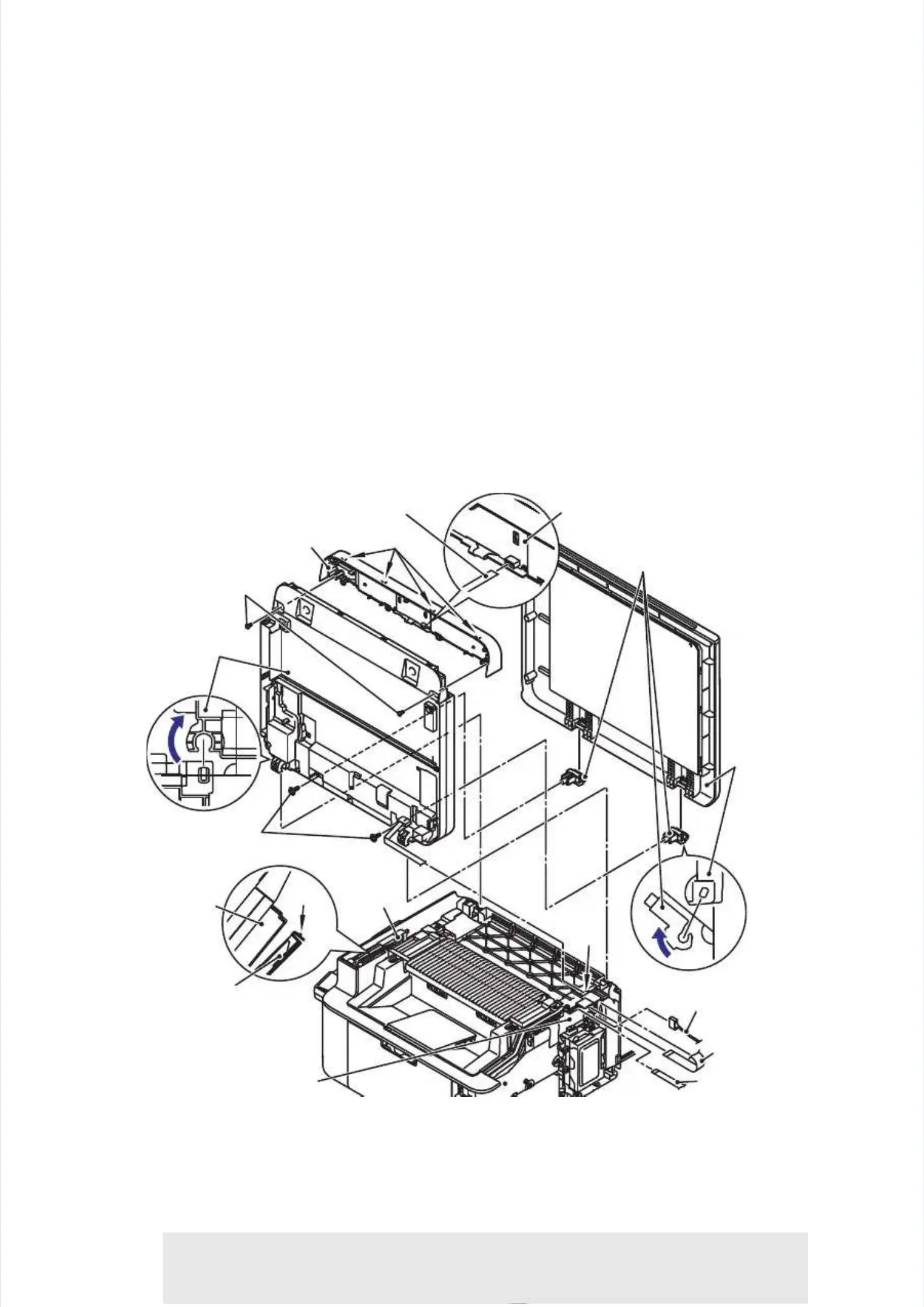
7.47.4 Document scanner unit / Document cover (oDocument scanner unit / Document cover (only for models without ADF unit)nly for models without ADF unit)
(1)(1) OpeOpen the n the docdocumeument snt scancanner uner unitnit..
(2)(2) DiscoDisconnect the Cnnect the CIS flat cablIS flat cable, the docue, the document scament scanner motonner motor harnessr harness, and the pa, and the panel flatnel flat
cable from the main PCB cable from the main PCB ASSYASSY, then pull out the , then pull out the CIS flat cable from CIS flat cable from the hole.the hole.
(3)(3) ReleaRelease the hook ose the hook of the pull-f the pull-arm, and rarm, and remove it fremove it from the docuom the document scament scanner uninner unit.t.
(4)(4) Open thOpen the docume document scanent scanner uniner unit 90 degrt 90 degrees and rees and remove iemove it by pult by pulling it ling it up.up.
(5)(5) RemovRemove the two tae the two taptite biptite bind B M4x12 scnd B M4x12 screws. Rerews. Release the flease the four hookour hooks of the pans of the panel unit.el unit.
Disconnect the panel flat cable from the panel PCB ASSY to remove the panel unit fromDisconnect the panel flat cable from the panel PCB ASSY to remove the panel unit from
the document scanner unit.the document scanner unit.
(6)(6) Remove thRemove the two tape two taptite pan B Mtite pan B M4x14 scre4x14 screws to remows to remove the docuve the document covment cover from theer from the
document scanner unit (only for models without ADF unit).document scanner unit (only for models without ADF unit).
(7)(7) Remove thRemove the hinge froe hinge from the docum the document covement cover by tiltir by tilting it 120 degng it 120 degrees (onlrees (only for modely for modelss
without ADF unit). (2 locations)without ADF unit). (2 locations)
Fig. 2-17Fig. 2-17
Harness routing: Refer toHarness routing: Refer to “
“1.1.Frame R / main PCB ASSY / low voltage power supply PCB unitFrame R / main PCB ASSY / low voltage power supply PCB unit
/ fuser unit (DCP-15** series without fan, MFC-18** series without fan)/ fuser unit (DCP-15** series without fan, MFC-18** series without fan)””,, ““22.. Frame R / mainFrame R / main
PCB ASSY / low voltage power supply PCB unit / fuser unit (DCP-15** series with fan, MFC-PCB ASSY / low voltage power supply PCB unit / fuser unit (DCP-15** series with fan, MFC-
18** series with fan)18** series with fan)””,, ““3.3.Frame R / main PCB ASSY / low voltage power supply PCB unit /Frame R / main PCB ASSY / low voltage power supply PCB unit /
fuser unit (DCP-16** series, MFC-19** series)fuser unit (DCP-16** series, MFC-19** series)””andand ““77.. Panel flat cablePanel flat cable””..
Assembling Note:Assembling Note:
•• After After the the replacreplacement, ement, refer refer toto "
"33.. IF YOU REPLACE THE DOCUMENT SCANNER UNITIF YOU REPLACE THE DOCUMENT SCANNER UNIT
OR CIS UNIT" in chapter 3OR CIS UNIT" in chapter 3to enter the adjusted value of the laser unit.to enter the adjusted value of the laser unit.
Hinges (only for modelsHinges (only for models
without ADF unit)without ADF unit)
HooksHooks
DocumentDocument
covercover
(only for(only for
modelsmodels
withoutwithout
ADF unit)ADF unit)
Panel unitPanel unit
DocumentDocument
scanner unitscanner unit
Taptite pan B M4x14Taptite pan B M4x14
(only for models without ADF unit)(only for models without ADF unit)
Taptite bind B M4x12Taptite bind B M4x12
DocumentDocument
scanner unitscanner unit
Pull-armPull-arm
HookHook
Pull-armPull-arm
Panel PCB ASSYPanel PCB ASSY
Panel flat cablePanel flat cable
Panel flat cablePanel flat cable
CIS flat cableCIS flat cable
Document scannerDocument scanner
motor harnessmotor harness
Main PCB ASSYMain PCB ASSY
90°90°
120°120°
HoleHole
 Loading...