• The top end
of
upper knife driving rod 8
is
connected with upper knife driving lever 8 with pin
8,
then upper
knife driving lever
e gets oscillating movement.
• Upper knife
tD
is
connected upper knife holder
8,
gets oscillating movement with the intermediate action
of
upper
knife driving lever 8 and upper knife driving arm
(3.
2) Lower knife mechanism
• Lower knife
CD
is
fixed with lower knife holder
f)
and being pushed to upper knife
tD
with the pressure
of
lower
knife holder spring
fD
plays a role
of
edge trimming with upper knife
tD.
And lower knife holder guide
fB
plays role
of
positioning
of
lower knife
CD
and guide
of
lower knife holder
f).
12J
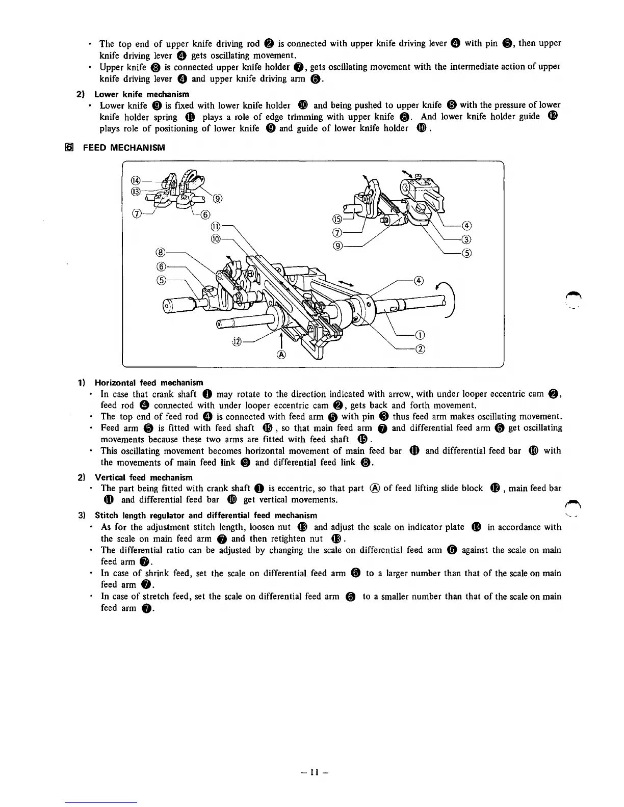
FEED MECHANISM
@
•.
~:v'
@)
~
I :
:
---
®
(j)- ®
1) Horizontal feed mechanism
@
@)
®
®
@
• In case that crank shaft 0 may rotate to the direction indicated with arrow, with under looper eccentric cam
8,
feed rod e connected with under looper eccentric cam • ' gets back and forth movement.
• The top end
of
feed rod 8
is
connected with feed arm
4D
with pin C) thus feed arm makes oscillating movement.
• Feed arm
CD
is
fitted with feed shaft
69,
so
that main feed arm
fj
and differential feed arm
(t
get oscillating
movements because these two arms are fitted with feed shaft
69.
• This oscillating movement becomes horizontal movement
of
main feed bar
fD
and differential feed bar
CD>
with
the movements
of
main feed link
CD
and differential feed link
tD.
2)
Vertical feed mechanism
• The part being fitted with crank shaft 0
is
eccentric,
so
that part @
of
feed lifting slide block
f)
, main feed bar
4)
and differential feed bar
f)
get vertical movements.
3)
Stitch length regulator and differential feed mechanism
•
As
for the adjustment stitch length, loosen nut
ell
and adjust the scale on indicator plate
CD
in
accordance with
the scale on main feed arm
fj
and then retighten
nut
Cl).
• The differential ratio can be adjusted by changing the scale on differential feed arm
(t
against the scale on main
feed arm
fj.
• In case
of
shrink feed, set the scale
on
differential feed arm
(t
to a larger number than that
of
the scale on main
feed arm
8.
• In case
of
stretch feed, set the scale
on
differential feed arm
(t
to a smaller number than that
of
the scale on main
feed arm
fj.
-
11-
\
..
_.
__