3.
DESCRIPTION
OF
MECHANISM
[j]
NEEDLE
BAR
MECHANISM
®
®-~-"
(j)------/
(@--
@------
CD
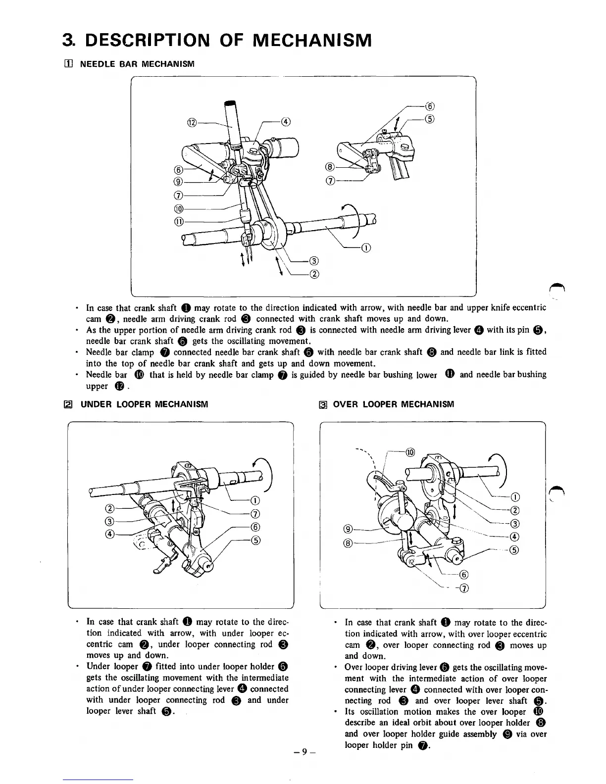
• In case that crank shaft 0 may rotate
to
the direction indicated with arrow, with needle bar and upper knife eccentric
cam
8 , needle arm driving crank rod 0 connected with crank shaft moves up and down.
•
As
the upper portion
of
needle arm driving crank rod
Ct
is
connected with needle
arm
driving lever 8 with its pin
~,
needle bar crank shaft
(t
gets the oscillating movement.
• Needle bar clamp • connected needle bar crank shaft
(t
with needle bar crank shaft (;) and needle bar link
is
fitted
into the top
of
needle bar crank shaft and gets up and down movement.
• Needle bar C) that
is
held by needle bar clamp
fj
is
guided by needle bar bushing lower
CD
and needle bar bushing
upper
f).
12J
UNDER
LOOPER
MECHANISM
• In case that crank shaft 0 may rotate to the direc-
tion indicated with arrow, with under looper ec-
centric cam
8,
under looper connecting rod C)
moves up and down.
• Under looper 8 fitted into under looper holder
(t
gets the oscillating movement with the intermediate
action
of
under looper connecting lever 8 connected
with under looper connecting rod
Ct
and under
looper lever shaft
•.
-9-
13]
OVER
LOOPER
MECHANISM
®
@---
-CD
~@
~®
-----@)
-®
L
_____
____,
• In
case
that crank shaft 0 may rotate
to
the direc-
tion indicated with arrow, with over looper eccentric
cam
8,
over looper connecting rod
Ct
moves up
and down.
•
Over looper driving lever
(t
gets the oscillating move-
ment with the intermediate action
of
over looper
connecting lever
8 connected with over looper con-
necting rod
C) and over looper lever shaft
•.
• Its oscillation motion makes the over looper
"'
describe an ideal orbit about over looper holder
(;)
and over looper holder guide assembly
CD
via over
looper holder pin
fj.