
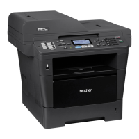
Do you have a question about the Brother MFC-8952DW and is the answer not in the manual?
Provides general specifications like print speed, resolution, and power consumption.
Details wired and wireless network support, including protocols and security.
Outlines machine life, part life, MTBF, and monthly volume recommendations.
Lists toner cartridge yields, drum unit life, and shelf life recommendations.
Covers paper handling, types, weights, sizes, and paper tray capacities.
Specifies unprintable and unscannable margins for various document sizes.
Information regarding telephone connectivity and features, if applicable.
Provides specifications specific to models equipped with FAX functionality.
Details copy speed, first copy out time, and resolution capabilities.
Specifies scanner resolution (optical and interpolated) and scanning speeds.
Describes direct printing capabilities and supported file formats via USB.
Overview of troubleshooting principles, common problems, and safety precautions.
Details machine components, paper paths, and operational aspects of key parts.
Lists and explains error codes, messages, and communication errors for diagnostics.
Provides detailed steps to diagnose and resolve common machine malfunctions and errors.
Essential safety warnings and precautions for handling machine parts during maintenance.
Illustrates the packing procedure for the machine and its accessories.
Lists and illustrates various screw types used in the machine for identification.
Provides specific tightening torque values for screws used in different assembly steps.
Details lubrication points, oil types, and quantities required for machine assembly.
Shows exploded views and names of gears within the machine for disassembly reference.
Illustrates the routing paths and connections for various harnesses within the machine.
Provides a visual flow chart outlining the disassembly and reassembly sequence for parts.
Detailed step-by-step instructions for disassembling various machine components.
Instructions for firmware installation, country setting, and EEPROM initialization after main PCB replacement.
Procedure for entering adjusted values for the laser unit after replacement.
Steps to reset the irregular power supply detection counter after replacing the LVPS PCB.
Procedure for initializing pre-discharge detection parameters after HVPS PCB replacement.
How to reset counters for periodic parts like drum, fuser, and paper feed kits.
Firmware installation and touch panel adjustment procedures for control panel replacements.
Procedure for acquiring white level data after replacing scanner or CIS components.
Describes how to enter and use maintenance mode for diagnostics and settings.
Covers functions like sleep mode settings and resetting periodic part counters.
Presents the main wiring diagram showing PCB connections and component layouts.
General safety warnings and precautions for performing maintenance tasks.
Lists parts that require periodic replacement and provides general replacement guidance.
Outlines steps to disconnect cables and remove accessories before disassembly.
Step-by-step instructions for disassembling and replacing the fuser unit.
Detailed procedure for removing and replacing the laser unit.
Instructions for disassembling and replacing the MP paper feeding kit.
Procedure for disassembling and replacing paper feeding kit 1.
Procedure for disassembling and replacing paper feeding kit 2.
Shows where the serial number label is located and how to read its format.
Steps to delete user setting information stored in the main PCB.
Step-by-step guide for installing the maintenance driver on a computer.


 Loading...