-11-
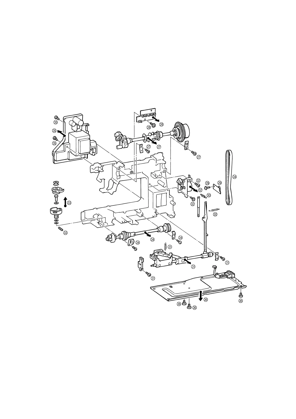
27. Remove the two screws securing the upper shaft metal, and the upper shaft assembly.
28. Remove the screw and the N.P. board assembly.
29. Remove the screw and the tension pulley holder.
30. Remove the two feed rod tension springs.
31. Remove the metal presser screw and horizontal feed shaft bracket screw, and then remove the horizontal feed
assembly.
32. Remove the two screws and FPM holder assembly.
33. Remove the screw and the outer rotary hook assembly.
34. Remove the two metal presser screws, and remove the lower shaft assembly and timing belt.
35. Remove the connector, the two screws and the power supply unit assembly.
36. Remove the three screws and base plate assembly.