PG.
SETTING INSTRUCTIONS AND MENU
All functions and controls on Brovind controllers are set by means of a 3-button keyboard found on the
controller box.
With the + and – keys, go to the menu you want and press the PR (program) key to enter the menu.
To make changes on the DCFF double controller, you have to enter the menu for the vibrator that needs to
be changed. To do this, select vibrator 1 or vibrator 2 with the + key or the – key and then enter the vibrator
menu with the PR key.
P. 34 shows a summary menu with a brief description of all the functions.
Press the + and – keys to display the basic work parameters on the controllers.
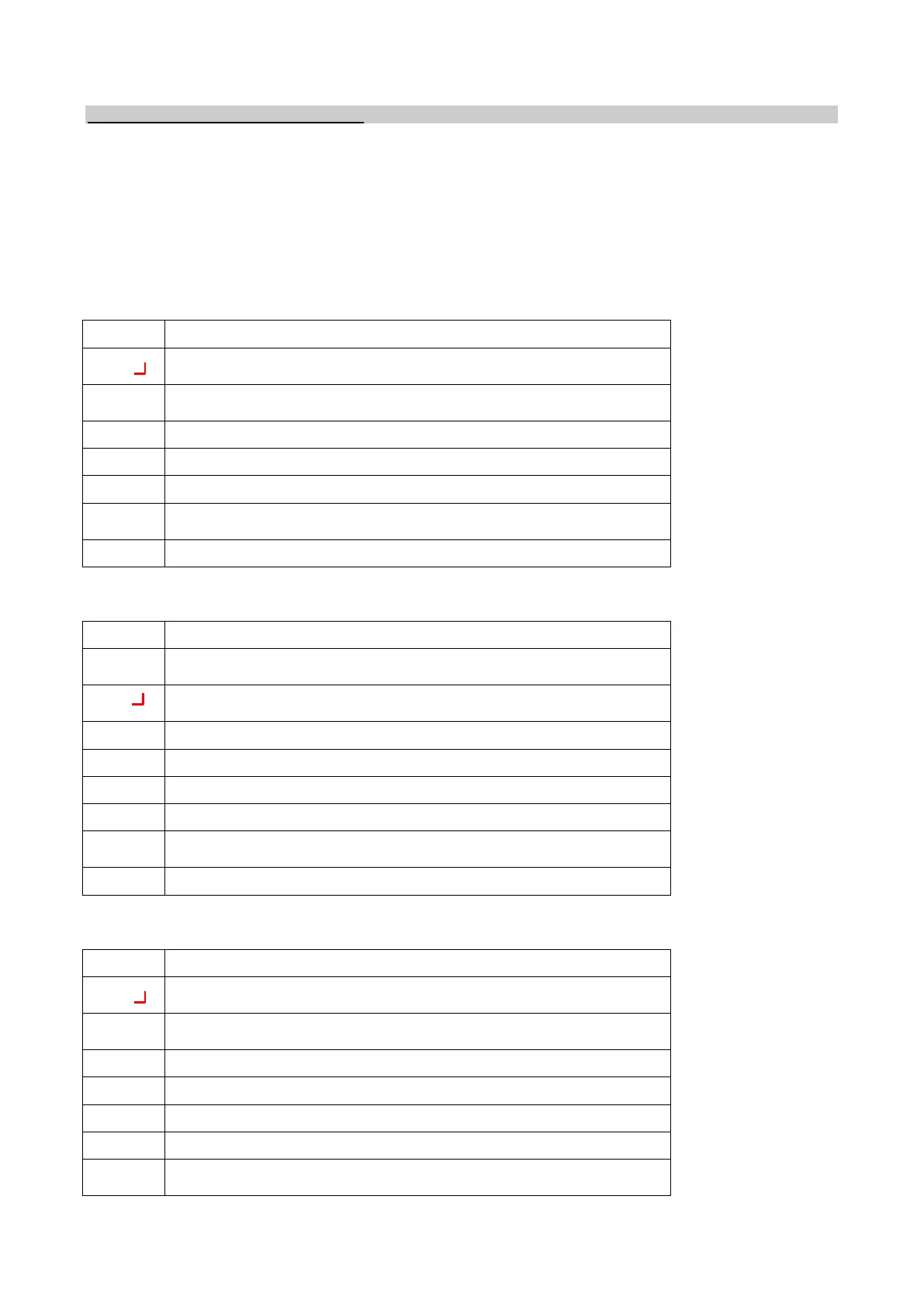
The following values are displayed for the CFF board:
CFF. Indicates type of controller
CFF. The dash at the end indicates that the logic function program is
enabled
CFF. The dot on the far right indicates that the pieces-counter function
is enabled.
Vi. Value from 0 to 100 indicating percentage of power delivered
A0. Set acceleration value of vibrator
AS. Indicates the acceleration value read by SRV02 probe (only if
SRV02 probe is present and enabled)
VA. Indicates the supply voltage (only if SRV02 probe is not enabled).
Table 06
The following values are displayed for the DCFF board:
1 ON. Indicates that we are on controller 1
1 ON. The dot on the far right indicates that the pieces-counter function
is enabled.
1 ON. The dash at the end indicates that the logic function program is
enabled
DCFF1 or DCFF2. Indicates type of controller
Vi. Value from 0 to 100 indicating percentage of power delivered
A0. Set acceleration value of vibrator
AS. Indicates the acceleration value read by SRV02 probe (only if
SRV02 probe is present and enabled)
VA. Indicates the supply voltage (only if SRV02 probe is not enabled).
Table 07
The following values are displayed for the CFV board:
CFV. Indicates type of controller
CFV. The dash at the end indicates that the logic function program is
enabled
CFV. The dot on the far right indicates that the pieces-counter function
is enabled.
Vi. Value from 0 to 100 indicating percentage of power delivered
A0. Set acceleration value of vibrator
I. Indicates consumed current
AS. Indicates the acceleration value read by SRV02 probe (only if
SRV02 probe is present and enabled)
Table 08