L
Linda LewisAug 6, 2025
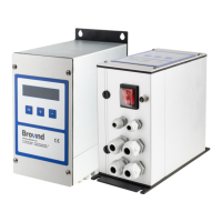
How to fix BROVIND Controller when the display doesn't light up?
- TtheresalopezAug 6, 2025
First, check that the power cable is properly connected to the mains. Next, open the controller box and ensure the power is correctly connected inside. Also, inspect the fuses on the board to see if they are in good condition. Finally, use a testing device to verify that power is reaching the switch on the controller box.