124
SYSTEM ANALYSIS
START CIRCUIT
Key Switch, ON position
12 V is applied to the “accessory” circuit. Key
switch ON:
• Switches 12 V to terminal “A” of key switch and
to the purple wires of the wire harnesses.
• Provides 12 V input to terminal 21 of J1-B EMM
connector and terminal “A” of starter solenoid.
Key Switch, START Position
Switches 12 V to terminal “S” of key switch and
12 V is applied to neutral safety switch.
Neutral Safety Switch (Remote Control)
Terminal “S” of the key switch provides 12 V (yel-
low/red) to the neutral safety switch (key switch in
START position).
A depressed or activated neutral safety switch (in
remote control) provides 12 V to the engine wire
harness yellow/red wire (key switch in START
position) and terminal 26 of EMM J-1A connector.
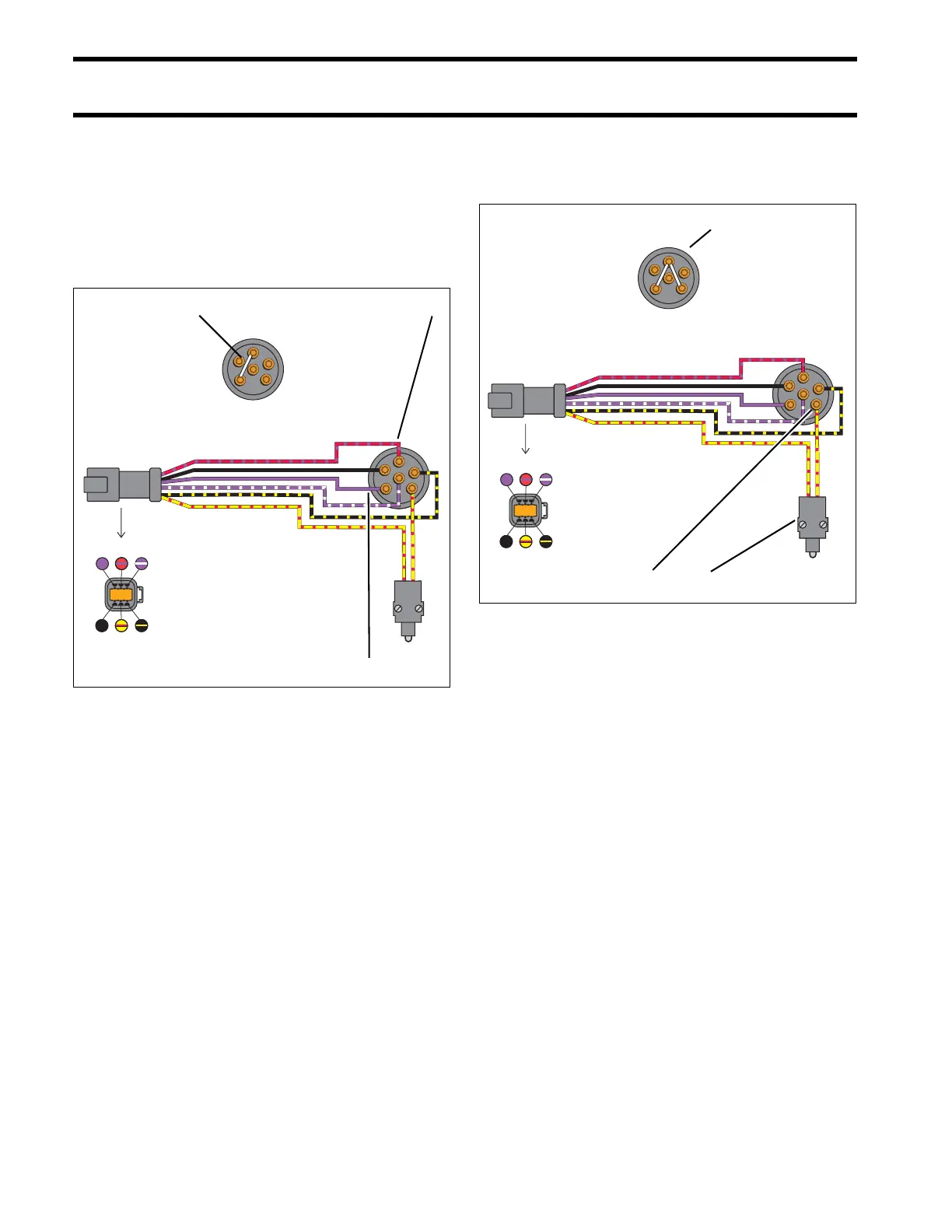
1. Key switch, ON position – Continuity between ter-
minals “B” and “A”
2. Terminal “B”, 12 V (Red/purple)
3. Terminal “A”, 12 V (Purple)
000691
B
M
M
C
A
S
M
B
S
A
C
M
M
B
S
A
C
M
M
B
S
A
C
M
456
123
1 2
3
1. Ignition switch, START position – Continuity
between terminals “B” and “A”; “B” and “S”
2. Terminal “S”, 12 V
3. Neutral safety switch
000691R
1
2 3
B
M
M
C
A
S
M
B
S
A
C
M
456
123