259
POWERHEAD
ASSEMBLY
10
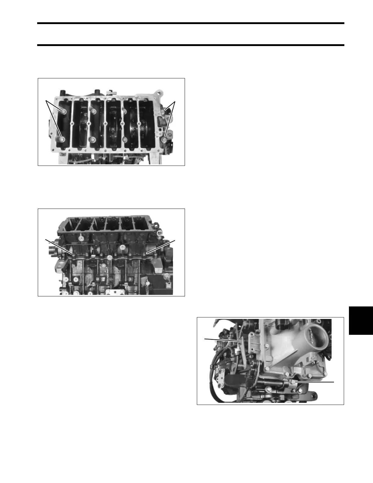
Torque main bearing screws in stages to 31 to 35
ft. lbs. (42 to 47.5 N·m). Begin with the center
screws and work outward in a spiral pattern.
Apply Triple-Guard grease to crankcase flange
screws. Install screws and torque to 60 to 84 in.
lbs. (7 to 9.5 N·m).
Test that the crankshaft spins freely without bind-
ing.
IMPORTANT: After powerhead has been
assembled, allow at least two hours for Gel-Seal II
to cure before running outboard.
General
Connect all crankcase recirculating hoses. Refer
to Recirculation Hose Routings and Check
Valve Diagrams – V4 on p. 213, Recirculation
Hose Routings and Check Valve Diagrams –
V6 on p. 211, or POWERHEAD VIEWS on p. 266.
Install pressure valve assembly. Refer to PRES-
SURE RELIEF VALVE SERVICING on p. 233.
Install the throttle body and reed plate assemblies.
Refer to INTAKE MANIFOLD on p. 196.
Lubricate shift linkage bosses at the base of the
crankcase with Triple-Guard grease. Insert bush-
ings into bosses.
Apply Triple-Guard grease to the shaft of the shift
lever assembly. Guide shaft through bushings in
crankcase.
Install shift rod lever and tighten retaining screw
60 to 84 in. lbs. (7 to 9.5 N·m).
Apply Triple-Guard grease to shoulder of shift arm
screw and Nut Lock to threads. Install arm, screw,
and washer and torque screw to 120 to 144 in.
lbs. (14 to 16 N·m).
1. Main bearing screws (6 on V4; 8 on V6) 005313
1. Flange screws (12 on V4; 16 on V6) 005306
11
11
1. Shift arm screw
2. Shift lever screw
005294
2
1