185
FUEL SYSTEM
FUEL COMPONENT TESTS
7
fuel pump uses 12 V circuit and the injectors use
55 V circuit.
Resistance Test
Disconnect the battery cables at the battery.
Use a digital multimeter to measure the injector
circuit and coil resistance.
Use electrical test probe kit, P/N 342677, and a
multimeter to check resistance. Wire harness
adaptor leads, P/N 342228 can be used to make
connection at EMM J1-B connector.
Measure resistance between pin 1 of injector con-
nector and the appropriate pin location of EMM
J1-B connector. Refer to engine wiring diagram
for specific EMM J1-B connector pin location for
the injector circuit being tested.
Fuel Supply
Fuel System Pressure Test
Relieve fuel system pressure. See Relieving Fuel
System Pressure on p. 189.
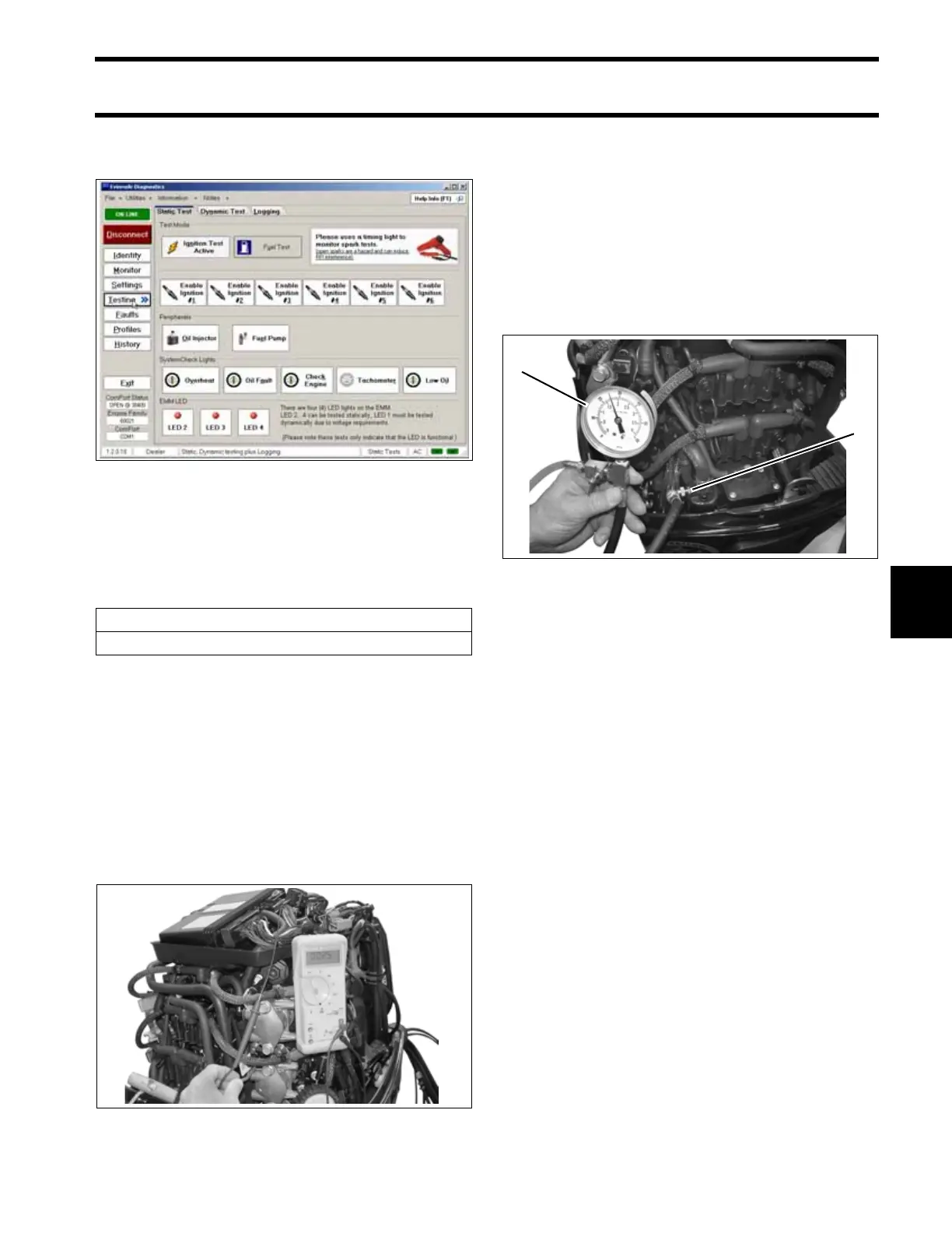
After relieving fuel system pressure, install a 0 to
60 psi (0 to 415 kPa) Fuel Pressure Gauge,
P/N 5007100 or equivalent, to the upper fuel pres-
sure test fitting.
START outboard and check pressure. System
pressure should be 20 to 35 psi (138 to 241 kPa).
Shut OFF outboard. Monitor pressure gauge.
Pressure should not drop below 15 psi (103 kPa).
IMPORTANT: If outboard does not run, prime
fuel system and crank outboard; check circulation
pump operation; check fuel system pressure.
Results:
Normal pressure
• Observe pressure reading after outboard is shut
OFF.
• Proceed to Lift Pump Pressure Test on
p. 187.
Pressure drops after outboard shut OFF
• Leaking fuel injector
• Leaking pressure regulator
• External fuel system leak
Static Tests Screen 005146
Fuel Injector Coil Resistance
2 to 3 Ω
@ 72°F (22°C)
005437
1. Fuel pressure gauge
2. Test fitting
005432
2
1