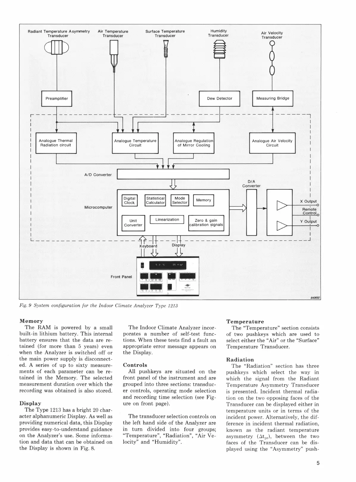
Radiant Temperature
Asymmetry
Air Temperature
Transducer Transducer
Surface Temperature
Transducer
Humidity
Transducer
Air
Velocity
Transducer
r---
I
I
I
Analogue Thermal
Radiation
circuit
L _
______
_
A/D
Converter
Microcomputer
Analogue Temperature
Circuit
Analogue Regulation
of
Mirror
Cooling
Zero
& gain
calibration
!)ignals
Front Panel
Fig. 9 Sy
stem
configuration for the Indoor Climate
Anal
yzer Type 1213
Memory
The
RAM is powered by a small
built-in
lithium
battery.
This
internal
battery
ensures
that
the
data
are
re-
tained
(for more
than
5 years) even
when
the
Analyzer is switched off or
the
main
power
supply
is disconnect-
ed. A series of
up
to
sixty measure-
ments
of each
parameter
can
be re-
tained
in
the
Memory.
The
selected
measurement
duration
over which
the
recording was
obtained
is also stored.
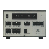
Display
The
Type
1213
has
a
bright
20
char-
acter
alphanumeric
Display. As well as
providing numerical
data,
this
Display
provides
easy-to-understand
guidance
on
the
Analyzer's use. Some informa-
tion
and
data
that
can
be
obtained
on
the
Display is shown in Fig.
8.
The
Indoor Climate Analyzer incor-
porates a
number
of self-test func-
tions.
When
these
tests
find a
fault
an
appropriate
error
message
appears
on
the
Display.
Controls
All pushkeys are
situated
on
the
front panel of
the
instrument
and
are
grouped
into
three
sections:
transduc-
er controls, operating mode selection
and
recording
time
selection (see Fig-
ure on
front
page).
The
transducer
selection controls
on
the
left
hand
side
of
the
Analyzer are
in
turn
divided into four groups;
"Temperature",
"Radiation", "Air Ve-
locity"
and
"Humidity".
------,
Analogue Air Velocity
Circuit
D/A
Converter
I
I
I
I
I
X Output
Re~ote
Control
I
Y Output
I
I
--
-------------
_j
840692
Temperature
The
"Temperature"
section consists
of two pushkeys which are used
to
select
either
the
"Air" or
the
"Surface"
Temperature
Transducer.
Radiation
The
"Radiation" section
has
three
pushkeys which select
the
way in
which
the
signal from
the
Radiant
Temperature
Asymmetry
Transducer
is presented.
Incident
thermal
radia-
tion
on
the
two opposing faces of
the
Transducer
can
be displayed
either
in
temperature
units
or in
terms
of
the
incident
power. Alternatively,
the
dif-
ference in
incident
thermal
radiation,
known as
the
radiant
temperature
asymmetry
(6tpr), between
the
two
faces of
the
Transducer
can
be dis-
played using
the
"Asymmetry" push-
5
 Loading...