checked, before measurements are made,
to
ensure that they have not become
scratched. Damaged
Windshields should be replaced as follows:
1.
Unscrew the retaining ring which holds the Windshield in position.
2.
Remove the damaged Windshield and replace with a new Windshield.
3.
Replace the retaining ring and screw tightly.
4.
Repeat
for
the Windshield on the other side
of
the Transducer
if
necessary.
A set
of
16 Windshields is supplied with the Radiant Temperature Asymmetry Trans-
ducer.
Additional sets can be ordered using
BrOel
& Kjrer order number UA 0851.
4.6.3. Range
of
Radiant Temperature Measurements
The range over which
plane radiant temperature measurements can be made using the
Radiant Temperature Asymmetry Transducer is dependent upon the air temperature
(ta)
and is given by the relationship:
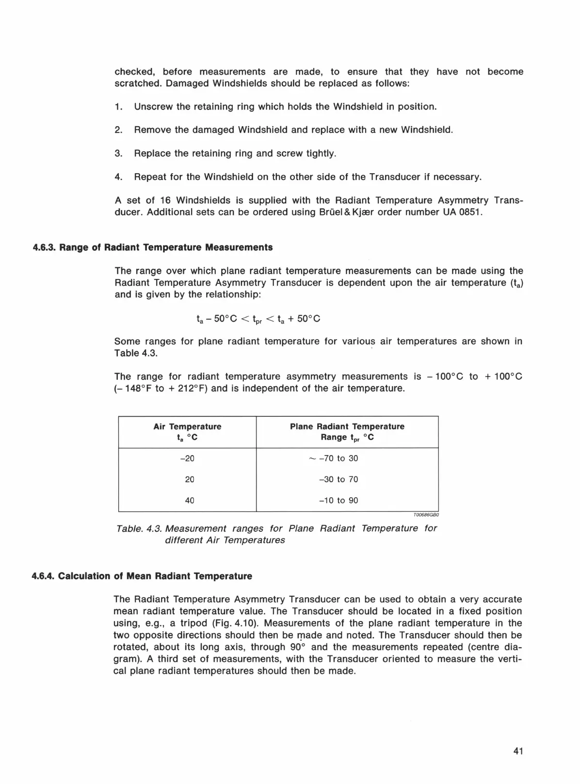
Some ranges
for
plane radiant temperature
for
various air temperatures are shown in
Table 4.3. ·
The range
for
radiant temperature asymmetry measurements is - 1
ooo
C to + 1
ooo
C
(-
148° F to + 212°
F)
and is independent
of
the
air
temperature.
Air
Temperature
Plane Radiant
Temperature
ta
oc
Range
tpr
°C
-20
--
-70
to 30
20
-30
to 70
40
-10
to 90
T00686GBO
Table. 4.3.
Measurement
ranges
for
Plane
Radiant
Temperature
for
different
Air
Temperatures
4.6.4.
Calculation
of
Mean Radiant Temperature
The Radiant Temperature Asymmetry Transducer can be used
to
obtain a very accurate
mean radiant temperature
value. The Transducer should be located in a fixed position
using, e.g., a tripod (Fig.
4.1
0).
Measurements
of
the plane radiant temperature in the
two opposite directions
should then be 'T'ade and noted. The Transducer should then be
rotated, about its
long axis, through 90° and the measurements repeated (centre dia-
gram). A third set
of
measurements, with the Transducer oriented to measure the verti-
cal plane radiant temperatures should then be made.
41
 Loading...