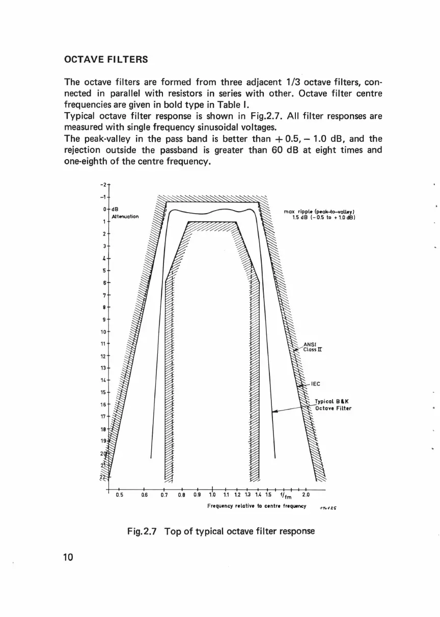
OCTAVE FILTERS
The octave filters are formed from
three
adjacent
1/3
octave filters, con-
nected
in
parallel with resistors
in
series with other. Octave filter centre
frequencies are given
in
bold
type
in
Table
I.
Typical octave filter response
is
shown
in
Fig.2. 7.
All
filter responses are
measured with
single frequency sinusoidal voltages.
The peak-valley in
the
pass band
is
better
than
+
0.5,-
1.0 dB, and
the
rejection outside
the
passband
is
greater
than
60
dB
at
eight times and
one-eighth
of
the
centre frequency.
10
-2
-1
0
dB
Attenuation
max rippl• (p•ak-to-vaU.yl
1.5
dB
(-
0.5 to + 1.0 dB)
10
11
12
13
14
15
16
17
18
19
ANSI
Class
II
0.5
0.6
0.7 0.8 0.9
1.0
1.1
1.2
13
1.4 1.5
f/fm 2.0
Fr•qu•ncy
r•latin
to
c•ntr•
fr~u.ncy
Fig.2.7
Top
of
typical octave filter response
Typical B&K
Octave
Filter
 Loading...