1.
INTRODUCTION
The
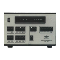
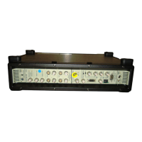
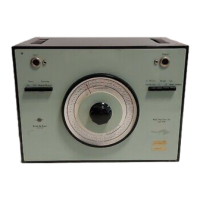
Filter Sets Types
1614
and
1615
are a development
of
the
older design
(Type 1612).
The
filter performance
is
generally improved and
the
Type
1614
includes extra filters
at
both low and high frequencies. Both
1614
and
1615
contain
the
sound weighting networks A,
8,
C,
and
the
more recently
introduced D network.
The
Filter Sets are primarily designed for vibration and acoustic frequency
analysis, and have specifications and tolerances which conform
to
the
following standards:
IEC
225
1966
ANSI S1.11-1966
(1/3octaveCiasslll,
1/1 octave Class II)
DIN
45652
The filters are band-pass filters, with
1/3
octave bandwidths. The filter
centre frequencies are spaced
1/3
octave apart, and filter selection
is
by a
50
- position switch
on
the
front
panel.
In
the
octave mode, 3 adjacent
1/3
octave filters are connected such as
to
produce a 1/1 octave bandwidth.
Filter selection
is
either manual
or
by
remote control, enabling synchroniza-
tion
with
other
equipment.
Linear ranges and
the
A,
8,
C,
and D networks are also selected by
the
50-
position switch.
The
input
and
output
to
the
filters can be connected
to
a wide range
of
terminating impedances.
For
Field measurements provision
is
made for 12 V
DC
operation.
Frequency analysis over a very wide frequency range can be accomplished
with
the
Filter
Set
in conjunction with a 8 & K Sound and Vibration
Measuring amplifier
Type
2606
or
Type
2603
or
the
8 & K Sound
Level
Meters.
1/3
octave
or
1/1 octave bands
of
random noise may also be
produced by using
the
Filter
Set
in conjunction with
the
8 & K Random
Noise Generator
Type
1402. These and
other
typical uses
of
the
Filter
Set
are briefly mentioned in Chapter 4
of
this Manual.
3
 Loading...
