ATTENUATOR
OUTPUT:
Set
MATCHING
IMPEDANCE in position
"Attenuator"
and
adjust
to
the appropriate signal level
by
OUTPUT
LEVEL
potenti-
ometer and
ATTENUATOR.
LOAD:
Set MATCHING IMPEDANCE
to
a value
as
near
as
possible
to
that
of
the load impedance, and adjust
to
appropriate signal level by
OUTPUT
LEVEL
potentiometer.
8.
USE WITH
LEVEL
RECORDER TYPE
2305
When the B & K Level Recorder
Type
2305
is
used
in
an
integrated
measuring system including the
Band-Pass
Filter
Set the filters and
weighting networks
of
the l_atter
can
be
selected automatically in succession
via the Level Recorder. The setting
up
and adjustment
of
the Recorder's
single chart automatic stop and the synchronization
of
filter
switching. and
recording paper calibration
is
as
given below:
Interconnect the Recorder
7-pole
REMOTE
CONTROL
socket
with
the
Filter
Set's REMOTE CONTROL socket
by
using the remote control cable
(AQ0019)
see
Fig.4.7.
1.
Insert the desired type
of
frequency calibrated paper and
mount
pen
or
sapphire.
If
necessary,
see
in$truction manual
for
the Level
Recorder.
Fi
Iter
Set
Level
Recorder
-
1614
or
1615
1-
~------------------------------_.
2305
-1691()()
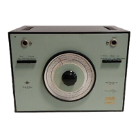
Fig.4.7 Filter
Set
Type 1614/15 combined
with
Level Recorder Type 2305
using remote control cable
AQ
0019
31
 Loading...