WEIGHTING NETWORKS
The A, B and C weighting networks are internationally standardized (IEC
179 for precision sound
level
meters) and their use
is
well-known
in
sound
measurement.
The
D network was more recently introduced, and complies
to
the
DIN
standard and
to
the
proposed
IEC
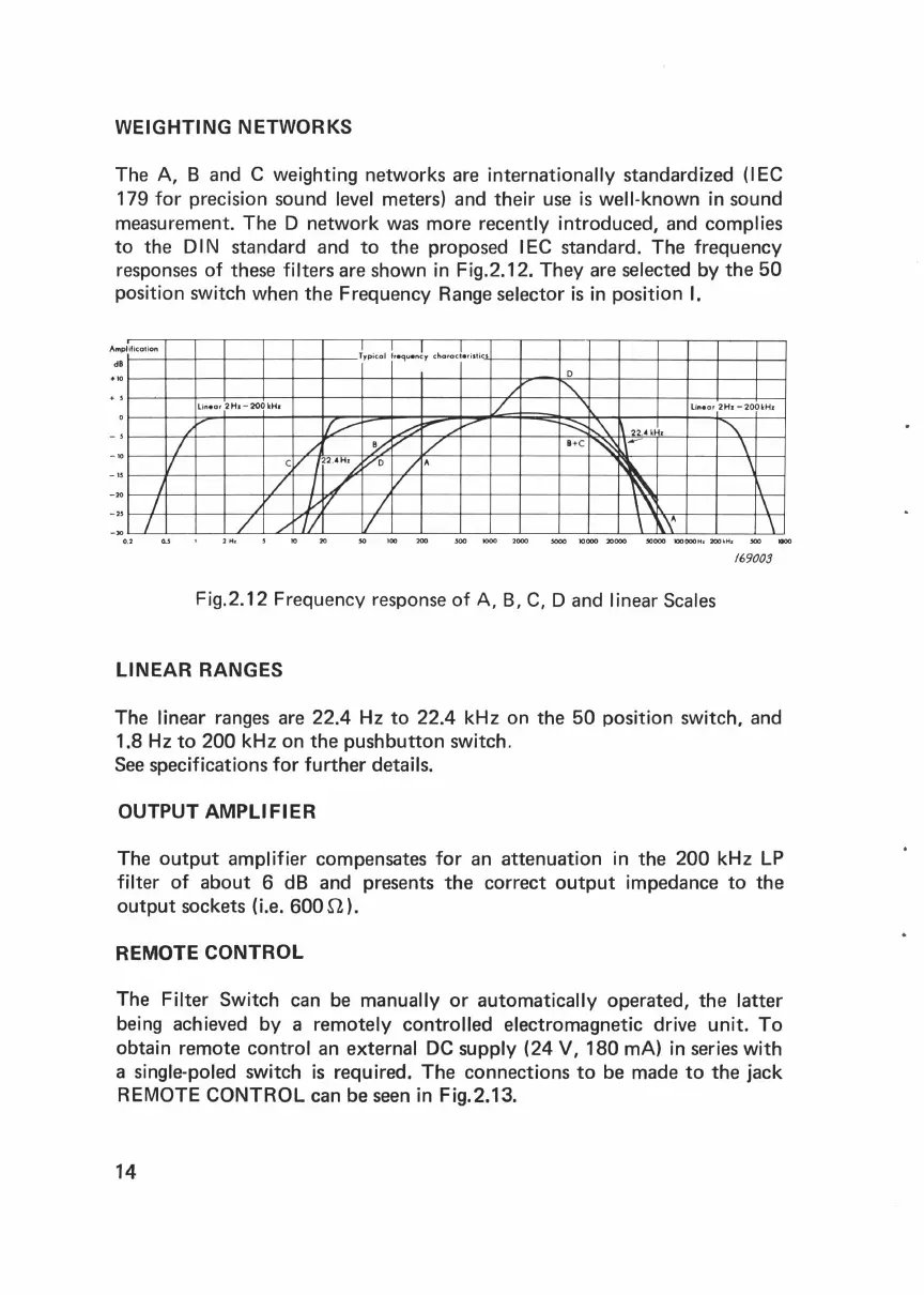
standard. The frequency
responses of these
filters are shown
in
Fig.2.12. They are selected by
the
50
position switch when
the
Frequency Range selector
is
in
position I.
Am
plificotion
dB
-JO
0.2
I
I
I
~ypicol
!requenly
chorac!•ristic
linear
2
Ha-
200
kH•
/~
'£-.--
~
F""""'/
..,.,....
I
/.
~;...'
v
v
C/
I
22.4
'L,
:;--o
/"
/
1/
/
yV
/
/
./
~II
I
0
/ '\..
/__
lin•
or 2
Hr
-200
kHr
.....:::::::
~
1\
22
.
HH•
"'
B+C
~
l\-
\
~
'
~
\~
\
\ \'\ \
169003
Fig.2.12 Frequency response
of
A,
B,
C,
D and linear Scales
LINEAR RANGES
The linear ranges are 22.4
Hz
to
22.4 kHz
on
the
50
position switch, and
1.8
Hz
to
200
kHz on
the
pushbutton
switch.
See specifications for
further
details.
OUTPUT AMPLIFIER
The
output
amplifier compensates for an attenuation
in
the
200
kHz
LP
filter
of
about
6
dB
and presents
the
correct
output
impedance
to
the
output
sockets (i.e.
600i1).
REMOTE CONTROL
The Filter Switch can be manually
or
automatically operated,
the
latter
being achieved by a remotely controlled electromagnetic drive unit.
To
obtain remote control an external
DC
supply (24 V,
180
mA)
in
series with
a
single-poled switch
is
required.
The
connections
to
be made
to
the
jack
REMOTE CONTROL can be seen
in
Fig.2.13.
14
 Loading...