•
After
the
extra fitters have been inserted,
the
front
panel scale should be
changed. This
is
done
after
removing first
the
filter switch knob by means
of
an Allen Key,
then
the
plastic cover which
is
secured by 4 plastic pegs held
by spring clips, and
last
the
filter switch pointer.
The
scale
is
held by
two
screws. After changing
the
scale and replacing
the
pointer,
the
pointer
position should be checked
in
the
following way:
The
top
two
pins no. 3 and 4
of
the
remote control socket should show an
open circuit
in
all
except
one
position
of
the
filter switch. This position
is
when
the
2
Hz
filter
is
selected. Hence an
ohmmeter
or
lamp and battery
connected
to
these
two
pins will enable
the
switch pointer position
to
be
set
correctly.
The
plastic cover should be replaced carefully
to
avoid breaking
the
pins.
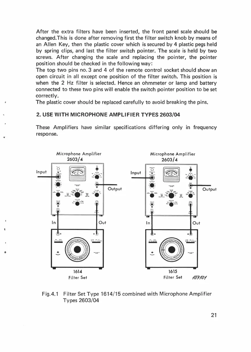
2.
USE
WITH MICROPHONE AMPLIFIER TYPES 2603/04
These Amplifiers have similar specifications differing only
in
frequency
response.
Input
Microphone
Amplifier
2603/4
--
¥
-"-
i
'=
-~·:.f.
·
~··
.2..
.,~
..
'r..
·-
In
1614
Filter
Set
Out
Output
..
In
Microphone
Amplifier
2603/4
1615
Filter
Set
Out
Fig.4.1 Filter
Set
Type
1614/15
combined with Microphone Amplifier
Types
2603/04
21
 Loading...