Do you have a question about the BRUEL & KJAER PULSE 3560-B and is the answer not in the manual?
Critical safety warnings for operating the equipment, including handling voltages and maintenance.
Outlines the manual's structure, content, and how to use it effectively.
Details the minimum and recommended PC specifications for optimal PULSE performance.
Explains how to establish a network connection between the PC and the PULSE front-end.
Steps to prepare the PC system before installing the PULSE software.
Guides through the step-by-step installation process of the PULSE software.
Details the process for fulfilling software licenses for PULSE applications.
Instructions for setting up the PULSE hardware components and connections.
Guides the user through configuring the front-end system and network settings.
Details the setup process for a single PULSE front-end unit.
Instructions for setting up multi-frame PULSE front-end systems.
Introduces the tool for managing and monitoring front-end connections.
Describes the automated self-test procedures for PULSE system modules.
Guides through testing the analog hardware components of the PULSE system.
Provides steps for diagnosing and resolving common network connectivity issues.
Explains how to use the test program for system verification and fault finding.
Defines the IDAe system and its core features and components.
Presents a general overview of the available PULSE hardware configurations.
Introduces the Dyn-X range of input modules and their advanced capabilities.
Addresses common grounding issues and provides solutions for noise reduction.
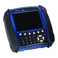
Describes the features, specifications, and operation of the 3560-B unit.
Explains the function of switches and indicators on the 3560-B front panel.
Details the features, specifications, and operation of the 3560-C unit.
Describes the 3560-D unit for multichannel data acquisition.
Details the 3560-E unit for multichannel data acquisition.
Explains the specifications and operation of the Type 2826 power supply module.
Describes the LAN interface module for network connectivity.
Details the 100 Mbit controller module for system integration.
Describes 5/1-channel input/output controller modules.
Details 5/1-channel Dyn-X I/O controller modules.
Describes I/O modules with integrated generators for signal output.
Details Dyn-X I/O modules with generators for signal output.
Describes 6/1-channel input/output modules.
Describes the 6-channel Dyn-X module for charge and CCLD inputs.
Details the 12-channel input modules.
Describes the 6-channel input modules.
Details the 12-channel Dyn-X input modules.
Describes the 6-channel Dyn-X input modules.
Details the generator module with 4/2 input channels and 2 output channels.
Describes the generator module with 2/1 input channels and 1 output channel.
Details the Auxiliary Input/Output connector and its functions.
Explains the RS-232 serial interface connector for IP addressing and testing.
Describes the BNT connector for signal input and tacho probe power.
Details the BNC/TNC input connectors for signal input.
Explains the BNC output connector for signal output.
Describes the 7-pin LEMO connector for various signal inputs.
Details the D-sub connectors used for input channels.
Explains overload indications and their causes on input/output modules.
Lists and describes various signal cables and connectors for system setup.
Details accessories required for LAN connectivity.
Lists power-related accessories and cables for system operation.
Describes accessories for mounting the system in a rack.
Lists miscellaneous accessories for the PULSE system.
Details the hardware components required for wireless LAN setup.
Lists accessories for enhancing wireless LAN capabilities.
Explains different system and antenna setup configurations for wireless LAN.
Provides instructions for installing the wireless LAN system.
Explains the importance and benefits of regular equipment calibration.
Outlines calibration and maintenance services offered by Br¸el & KjÊr.
Lists the types of calibration available for PULSE modules.
Lists relevant safety, EMC, and environmental compliance standards.
Provides general specifications for PULSE system types.
Details specifications for input channels, including Standard 24-bit and Dyn-X.
Instructions for handling system faults that affect safety.
Guidance for addressing functional faults without safety implications.
Details network connection setup using 10 base 2 for Type 7533.
Explains how to connect synchronization cables for multi-frame setups.
Lists input specifications for the discontinued Type 7533 module.
Lists discontinued DSP-based hardware components.
Lists discontinued IDA modules and their limitations.
| Brand | BRUEL & KJAER |
|---|---|
| Model | PULSE 3560-B |
| Category | Measuring Instruments |
| Language | English |