Do you have a question about the BRUEL & KJAER VIBROCONTROL 920 and is the answer not in the manual?
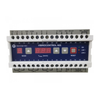
Monitors power supply, microprocessor, and sensor status via LED and relay.
Describes the instrument's self-test procedure upon power-up.
Explains how to change the instrument's operating mode using the MODE button.
Details the three-digit LED display for measurements and parameters.
Defines settings for LED display duration and brightness.
Describes OK error, LIM 1, and LIM 2 error signal behavior.
Explains the function of the Reset button in normal and parameter modes.
Details how to save parameter changes by pushing MODE and Reset buttons.
Describes the self-test procedure for LED displays and alarm LEDs.
Explains how the program version is shown on the displays.
Details how calibration constants are displayed.
Explains the format and signaling of error messages.
Guides on how to view parameter values using the MODE and arrow buttons.
Details the process for modifying parameter values via buttons.
Covers parameters for range allocation and limit values in Group 1.
Details parameters for sensor sensitivity, correction factor, and output range.
Explains service parameters like sensor voltage, temperature, and amplification.
Provides general instructions for installing the VIBROCONTROL 920 unit.
Details proper methods for connecting cable shields for interference-free operation.
Explains the importance of a low-resistance and interference-free ground connection.
Specifies methods for real panel and rail mounting, including dimensions.
Provides instructions for cleaning the device in a de-energized state.
| Brand | BRUEL & KJAER |
|---|---|
| Model | VIBROCONTROL 920 |
| Category | Measuring Instruments |
| Language | English |