FILTER
TRANSIENT
RESPONSE
The
filter inputs are
all
connected
to
the
input
terminal
in
parallel so
that
during an analysis when
the
filter set
is
being scanned, there are no filter
transients.
The
transient response
of
filters
is
actually quite complex,
depending
on
the
input
waveform as well as
the
type
of filter,
but
normally
need
not
be
taken
into
account
for
measurements with
the
1614/15.
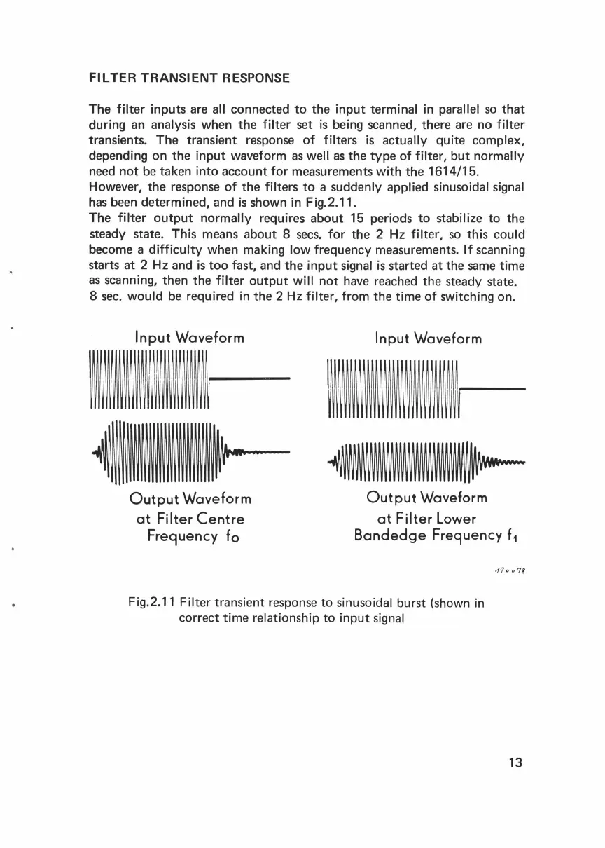
However,
the
response
of
the
filters
to
a suddenly applied sinusoidal signal
has been determined, and
is
shown
in
Fig.2.11.
The
filter
output
normally requires
about
15 periods
to
stabilize
to
the
steady state. This means
about
8 sees.
for
the
2 Hz filter, so this could
become a difficulty when making
low frequency measurements. If scanning
starts
at
2 Hz and
is
too
fast, and
the
input
signal
is
started
at
the same time
as scanning,
then
the
filter
output
will
not
have reached
the
steady state.
8 sec. would be required
in
the
2
Hz
filter, from
the
time
of
switching on.
Input
Waveform
Input
Waveform
-~~~--
\\\\111\\~,.....-
Output
Waveform
Output
Waveform
at
Filter
Centre
Freguency
fo
at
Filter
lower
Bandedge
Freguency
f
1
Fig.2.11 Filter transient response
to
sinusoidal burst (shown
in
correct
time
relationship
to
input
signal
410
0 78
13
 Loading...