The frequency
range
of
the 2603
is:
"Linear"
2
Hz-
40 kHz ±0.5 dB relative
to
1000 Hz
5
Hz-
20 kHz ±0.3 dB relative
to
1000 Hz
and
of
the 2604:
"Linear"
10
Hz-
200 kHz ±0.5 dB relative
to
1000 Hz
20Hz-100kHz
±0.3 dB relative
to
1000Hz
As
seen
the 2603 covers
range
I,
and
up
to
40 kHz
of
range
II
of
the 1614
and
the complete
range
of
the 1615. The 2604 covers
range
I
of
the 1614
and
the complete
range
of
the 1615,
but
not
under
10Hz
in
Range
II
of
the
1614.
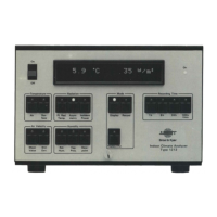
A
typical measuring set-up
of
the 1614/15 and 2603/04
is
shown in Fig.4.1.
The system
can
be
used
for
sound
and
vibration analysis
or
for
analysing
voltage waveforms.
MEASURING
ARRANGEMENT
1.
Set up the Microphone
Amplifier
on the desired measuring arrange-
ment.
2.
Wire up
Band-Pass
Filter Set
and
Microphone
Amplifier
according
to
Fig.4.1.
3. Set FREQUENCY
RESPONSE
SWITCH respective WEIGHTING
NETWORK
of
Microphone
Amplifier
to
"External
Filter".
4. Set control knobs
on
Band-Pass
Filter
Set.
POWER
"On"
SCANNING
"Manual"
Choose 1/3
or
1/1 octave bands
as
desired.
FILTER SWITCH
to
the
filter
at which the measurement should
be
carried out.
5.
Apply the
signal
to
be
analysed
to
the arrangement.
6.
Turn METER RANGE from the
"Ref"
position counterclockwise
until
the overload Indicator just shows overload. From this position
turn one step
clockwise. Indicator should now show no overload.
7. Set METER SWITCH
to
"R.M.S.",
"Average"
or
"Peak".
"Fast"
or
"Slow"
as
desired.
8. Set RANGE
MULTIPLIER
to
obtain suitable indicating meter
deflection, preferable between 10 and 20 dB on
scale.
22
•
 Loading...