2.
Set control knobs on Level Recorder:
POTENTIOMETER RANGE
dB"
POWER
MOTOR
PAPER
DRIVE
"Stand
by"
"On"
"On"
"Stop"
and
"Forward"
The switching moment
of
the Filter Switch
on
the
Band-Pass
Filter
Set
can
now be synchronized with the paper movement.
1.
Turn
the screw S shown in Fig.4.8
with
the aid
of
a screwdriver,
until
marking
cut
in the
screw
is
in its upper position.
2.
When
proceeding
from
above
set
control knobs on the Microphone
Amplifier
and
Band-Pass
Filter Set
as:
Microphone
Amplifier:
FREQUENCY RESPONSE SWITCH respective WEIGHTING NET-
WORK
to
"External
Filter"
z
X
Remote
Control
7-pol.
s
s
X
+60285
z
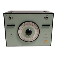
Fig. 4.8 Level Recorder Type 2305 with identification
of
Synchronising
Gear
Lever X, ScrewS
and
Finger
Wheel
Z.
32
 Loading...