+3
dB
+2
+ 1
0
1
-2
-3
/"'"
10
1\
!'...
-
....
l/
v
20
100
200
Tplerilnce
1--;-r-
'f
IEC 651
Type
1
/
-~
I-ll
•
r~
t f\tdl
~-
,.
.M
~,.,J!
,
~"-"'
...
~
..,..,.,
f'J"
..
~'-,
1\
-
- Without ZF
0020
1\
--
-lith
zr
0120
1\
1\
1 k
2k
10 k
20
k
Frequency (Hz)
830329
Fig. 3. Typical 0° free field frequency response
of
the complete
instrument
+3
dB
+2
+ 1
0
-1
-2
-3
/
/
10
........
'-
'~
'
,_
/~
,/
/
v
20
100
200
1 k
Tolerance
ANSI
S-
-~(
Type
1
A'
-1.4.-1971
l/
t---
II
"'
['..~
\
\
\
\
2k
10 k
Frequency (Hz)
'
20
k
830330
Fig.
4.
Typical diffuse field frequency response
of
the complete
instrument
Frequency
weighting
Four
built-in
frequency filters give
"A"
and
"C" weightings in accordance
with
IEC
651,
and
"Lin" (20 Hz
to
20
kHz)
and
"All-pass" (10 Hz
to
50
kHz).
The
AC
and
DC
output
signal
and
the
signal
sent
to
the
external
fil-
ter
set
are also frequency weighted.
Measuring
range
Six
attenuator
settings give 6 over-
lapping
70
dB
measuring ranges from
24
dB
to
130 dB. Use of
the
supplied
20
dB
Attenuator
ZF 0020 gives a
measuring range from
30
to
150 dB.
The
displayed value is
automatically
corrected
to
take
in
account
the
pres-
ence of
this
attenuator
.
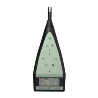
Display
The
comprehensive liquid crystal
display comprises four digits giving a
0,1
dB
resolution for display of
the
selected
measured
value
and
a 60
dB
quasi-analogue display with 2
dB
reso-
lution
for
continuous
visual monitor-
ing.
The
digital
and
quasi-analog dis-
plays are respectively
updated
once
and
64
times
per
second.
The
following warnings are also dis-
played:
t: overload is occuring
"":
overload
has
occured
BAT
(flashing):
battery
near
low level
BAT
(flashing) & t (non-resettable):
battery
depleted
t (non-resettable): illegal
setting
Fig. 5. Display
of
Type
2230
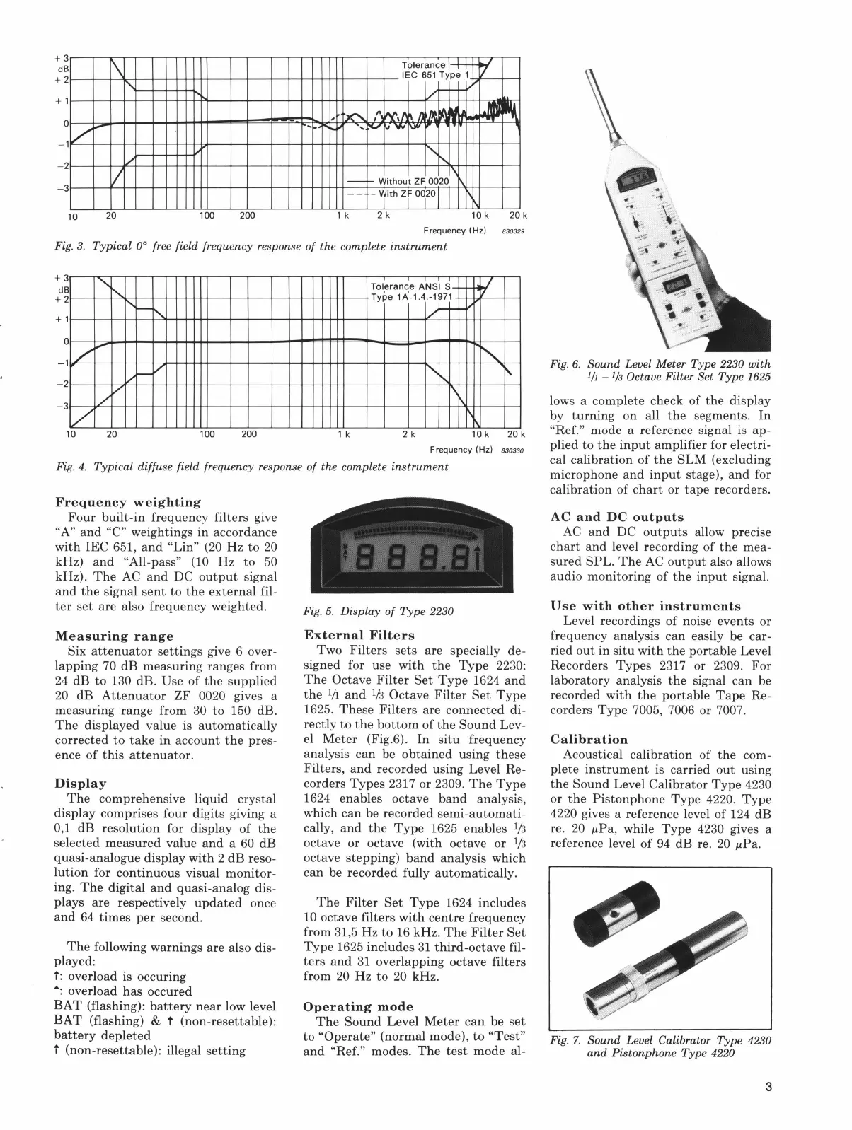
External
Filters
Two
Filters
sets
are specially de-
signed for use
with
the
Type
2230:
The
Octave
Filter
Set
Type
1624
and
the
l/1
and
lf
s Octave
Filter
Set
Type
1625.
These
Filters
are
connected
di-
rectly to
the
bottom
of
the
Sound
Lev-
el
Meter
(Fig.6).
In
situ
frequency
analysis
can
be
obtained
using
these
Filters,
and
recorded using Level Re-
corders
Types
2317 or 2309.
The
Type
1624 enables octave
band
analysis,
which
can
be recorded
semi-automati-
cally,
and
the
Type
1625 enables
lj
s
octave or octave (with octave or ljs
octave stepping)
band
analysis which
can
be recorded fully automatically.
The
Filter
Set
Type
1624 includes
10 octave filters
with
centre
frequency
from 31,5
Hz
to
16kHz.
The
Filter
Set
Type
1625 includes
31
third-octave
fil-
ters
and
31
overlapping octave filters
from
20
Hz
to
20
kHz.
Operating
mode
The
Sound
Level
Meter
can
be
set
to
"Operate" (normal mode),
to
"Test"
and
"Ref." modes.
The
test
mode
al-
\
Fig. 6.
Sound
Level Meter Type 2230 with
IJI
-
lj3
Octave Filter Set
Type
1625
lows a complete check of
the
display
by
turning
on all
the
segments.
In
"Ref." mode a reference signal is ap-
plied
to
the
input
amplifier for electri-
cal calibration of
the
SLM
(excluding
microphone
and
input
stage),
and
for
calibration of
chart
or
tape
recorders.
AC
and
DC
outputs
AC
and
DC
outputs
allow precise
chart
and
level recording of
the
mea-
sured
SPL.
The
AC
output
also allows
audio monitoring of
the
input
signal.
Use
with
other
instruments
Level recordings of noise events or
frequency analysis
can
easily be car-
ried
out
in
situ
with
the
portable Level
Recorders
Types
2317 or 2309.
For
laboratory analysis
the
signal
can
be
recorded with
the
portable
Tape
Re-
corders
Type
7005, 7006 or 7007.
Calibration
Acoustical calibration of
the
com-
plete
instrument
is carried
out
using
the
Sound
Level
Calibrator
Type
4230
or
the
Pistonphone
Type
4220.
Type
4220 gives a reference level of 124 dB
re.
20
JLPa,
while
Type
4230 gives a
reference level
of
94
dB
re.
20
JLPa.
Fig.
7.
Sound
Level Calibrator
Type
4230
and
Pistonphone Type 4220
3

 Loading...