Power Amplifiers Types 2716 and 2716-C –
User Manual
4
either turn down the input level or check the cooling arrangements. Above the maxi-
mum temperature, the amplifier mutes the input signal. Once the air-cooling lowers the
output heat and normal operating temperature is regained, the input signal is un-muted.
This indicator also illuminates when signals above 12kHz are continuously present at
full power at the output terminals. If this occurs, the input signal is muted and the
process cycles until the VHF signal is no longer present (see “VHF Protection” on
page 20).
5) Signal-present indicator: illuminates at 25 dB below full output signal
6) On indicator: the two bottom green “ON” LEDs indicate that the output circuits are
receiving the correct rail voltage.
7) Power switch: toggles mains power between on and off (see “Operating Voltage” on
page 9 and Chapter 5).
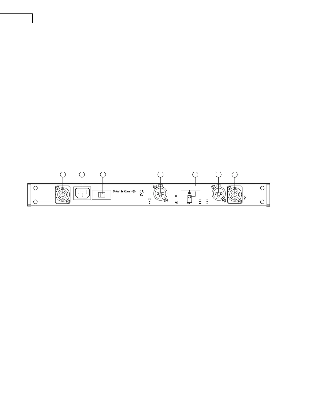
1.3.3 Rear Panel
Fig.1.3 Rear Panel
1) Output/Speaker connector: the Speakon
®
connector from Neutrik
®
may be unfamiliar
to some users. A full description is found in the operation section.
2) Clip limiter switch: turns the clip limiter on (switch IN position) or off (switch OUT
position).
3) Input signal XLR: Neutrik
®
Combojack features also ¼″ TRS phone jacks; pin 2 is
“hot”. See “Input connections” on page 11.)
4) Link and Polarity reverse switch: These two switches in the DIP-switch are used for
Link and Bridge operation (see Chapter 2).
5) Appliance inlet.
6) Voltage selector: Selects between nominal 230 V or 115V mains voltage.
LINK / BRIDGE A+B
STEREO
INPUT
CH.A
XLR
Pin 1
2
3
Scrn
Pos
Neg
1/4"
Sleeve
Tip
Ring
INPUT
CH.B
OUTPUT CH.A
BRIDGE
STEREO
Ser.N:o
Power Amplifier
Clip Limiter
On
Off
OUTPUT CH.B
1
5
6 3
4
3
1
030034
230/115V~50-60Hz
600 Watts Max.
230V~ 115V~
Voltage selector
Pin 1+ Spk+
2- Spk-
1+ CH.A+
1- CH.A-
2+ CH.B+
2- CH.B-
Removed!
BE169212.book Page 4 Tuesday, January 23, 2007 9:00 AM

 Loading...


