Introduction
14 Z33119_2_003
Figure3.2: Schema with BCU
3.2 Technical Data
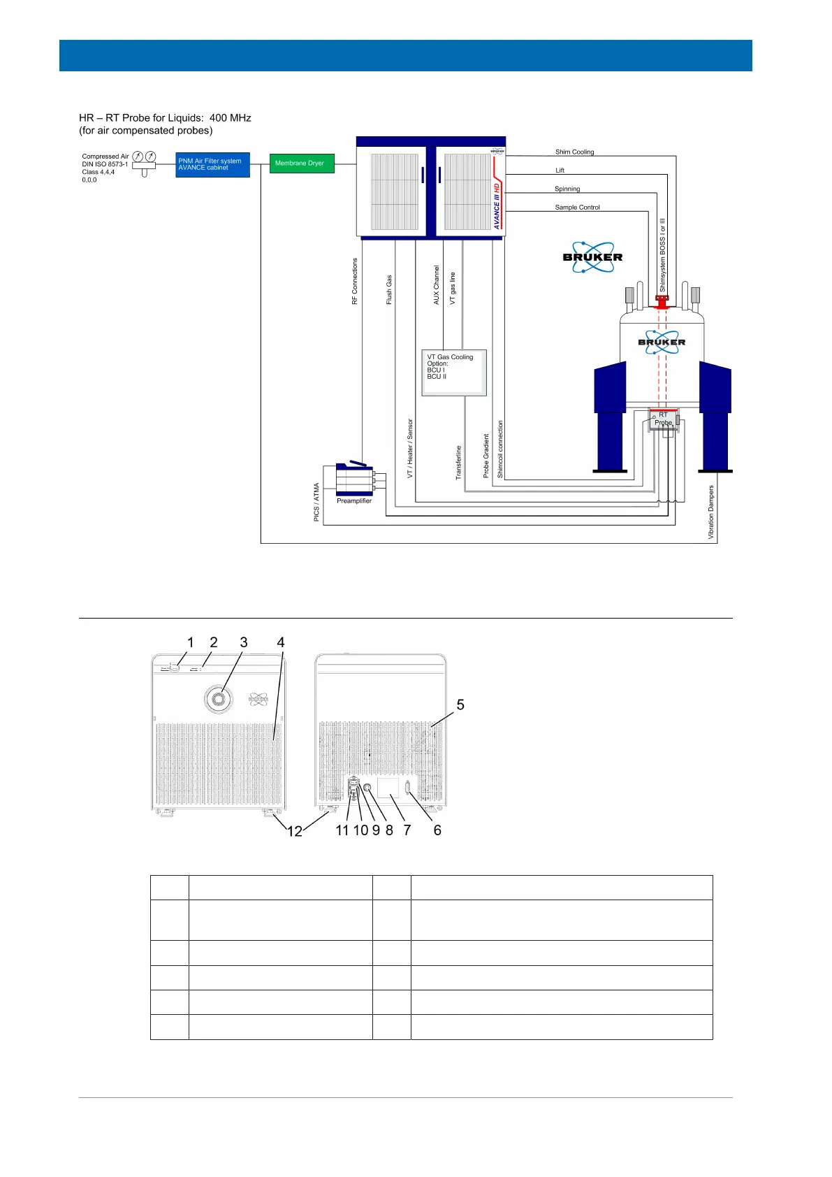
Figure3.3: View of the BCU of the front and the back.
1 Rotary switch 7 Rating plate
2 LEDs (2x) 8 Variable temperature (VT) gas IN Ø=8mm
(max. 6bar)
3 Transfer line – VT gas OUT 9 Main switch
4 Air inlet grid 10 Fuse (2 x 5 x 20mm 10AT)
5 Air outlet grid 11 Power socket
6 D-Sub 15 socket 12 Hexagon sockets (4x)
 Loading...