Model 771, 75, and 76-RH190 Transits 10
verticaltangentlock.
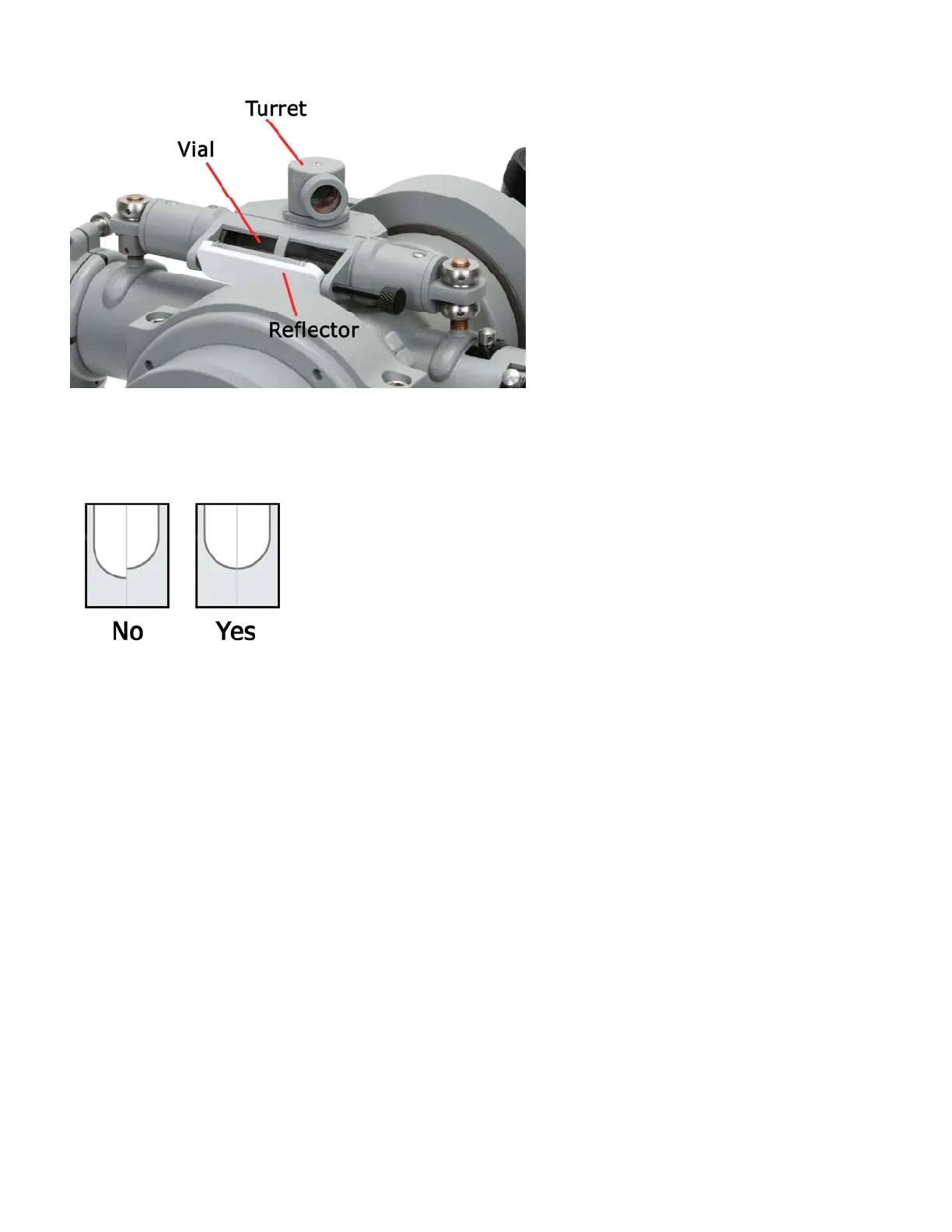
Thebubbleinthecoincidencevialop‐
erateslikeanyotherlevelvial,butthe
operatorviewsa“foldedimage”of
bothendsofthebubblesimultane‐
ously.Ifthetelescopeistilted,thetwo
bubbleimagesmoveinoppositedirec‐
tions.However,whenbothendsof
thebubblearebrought
“intocoinci‐
dence”(Figure2.5),thevialisdead
level.Youwillseesomethingsimilar
toFigure2.5bylookingintothevial’s
turret.Sincethehumaneyeisex‐
tremelyskillfulatdetectingeventiny
breaksinotherwisecontinuouslines,
thissystemmakesreadingthelevelextremelysensitiveandaccu‐
rate.
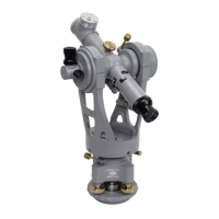
Rotatetheturretonthecoincidencevialsothatyoucanconven‐
ientlyviewthesplitimageofthebubbleinside.Areflectorhaving
onewhitesideandonemirroredsideisprovidedtohelpilluminate
theimage.Positionthereflectorforoptimalbubbleillumination.
1. Usingtheverticaltangentadjustmentscrew,bringthe
splitimageofthebubbleintocoincidence(Figure2.5).
2. Rotatethestandards180°sothatthetelescopeisnow
pointingintheoppositedirection.Ifthebubbleisoff
center,removeone‐halftheerrorwiththetwoleveling
screwswhicharelocateddirectlyunderthetelescope.
Removetheotherhalfoftheerrorusingtheverticaltan‐
gentscrew.Rememberthatyoucanseethebubbleby
lookingintothesideofthevialitselfratherthanintothe
turretwindow—thismayhelpyoudeterminewhichway
thebubblemustmove.
3. Nowrotate
thestandards90°sothatthetelescopeislo‐
cateddirectlyovertheotherpairoflevelingscrews.
Bringthebubbletocenter,usingonlythetwoleveling
screwsunderthetelescope.
4. Fromthisposition,rotatethestandards180°.Again,if
thebubbleisoffcenter,removeone‐halftheerrorwith
theverticaltangentscrew,andtheremainingone‐half
errorwiththetwolevelingscrewswhicharelocatedun‐
derthetelescope.
5. Repeatsteps2‐4,alternatingovereachpairofleveling
screws,untilthebubbleremainsincoincidenceinallfour
“compasspoint”positions.
Figure2.4
Notethatthetransit’sverti‐
calspindlemaybebrought
intoplumb(exactlyvertical)
evenifthecoincidencevial
itselfisnotcalibratedprop‐
erlywithrespecttothetele‐
scopebarrel.
Figure2.5