Model 771, 75, and 76-RH190 Transits 50
lightinginthereferenceinstrument’smaintelescope(orswitchthe
lightsourcefromoneinstrumenttotheother).
5.Lookthroughthetesttransit’scross‐axistelescopeeyepieceand
youshouldseethereferenceinstrument’sbacklitreticle.Whenyou
rotatethetesttransit’smaintelescope,youwillseeitscross‐axis
re‐
ticlerotateaswell.Bydoingthis,putthecross‐axisreticledirectly
intoregisterwiththereferenceinstrument’sreticle.Youcannow
makeanynecessaryadjustmentstothetesttransittobringthereti‐
cleimagespreciselyintoregister.Usethehorizontaltangentad‐
justmentscrewforhorizontal
adjustments,andusethetwoleveling
screwswhichareinlinewiththereferenceinstrumenttomakever‐
ticaladjustments.
6.Oncethetesttransit’scross‐axisispreciselyregistered
withthereferenceinstrument,rotatethemaintelescope180°.
Anyerrorinthecross‐axistelescopewillshowupasadevia‐
tionbetweenthetworeticles.Ifthereisanyerror,itmaybe
intheverticaldirection,horizontaldirection,orboth.Itis
necessarytoestimatethiserror,sinceingeneralwedonot
haveanangle‐measuringopticalwedgeinthefield.There‐
forewerelyonreticlegeometry.
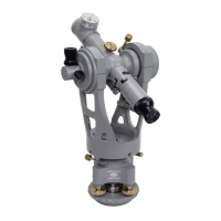
Weknowthatthewidthofareticlewireis5arcseconds,and
thegapbetweenthereticlepairis15arcsecondswide(Figure
4.7).Therefore,wecanmakeanestimateoftheobserveder‐
ror,rememberingthattheobservederroristwicetheactual
error.Thisfactmakestheerroreasiertosee.
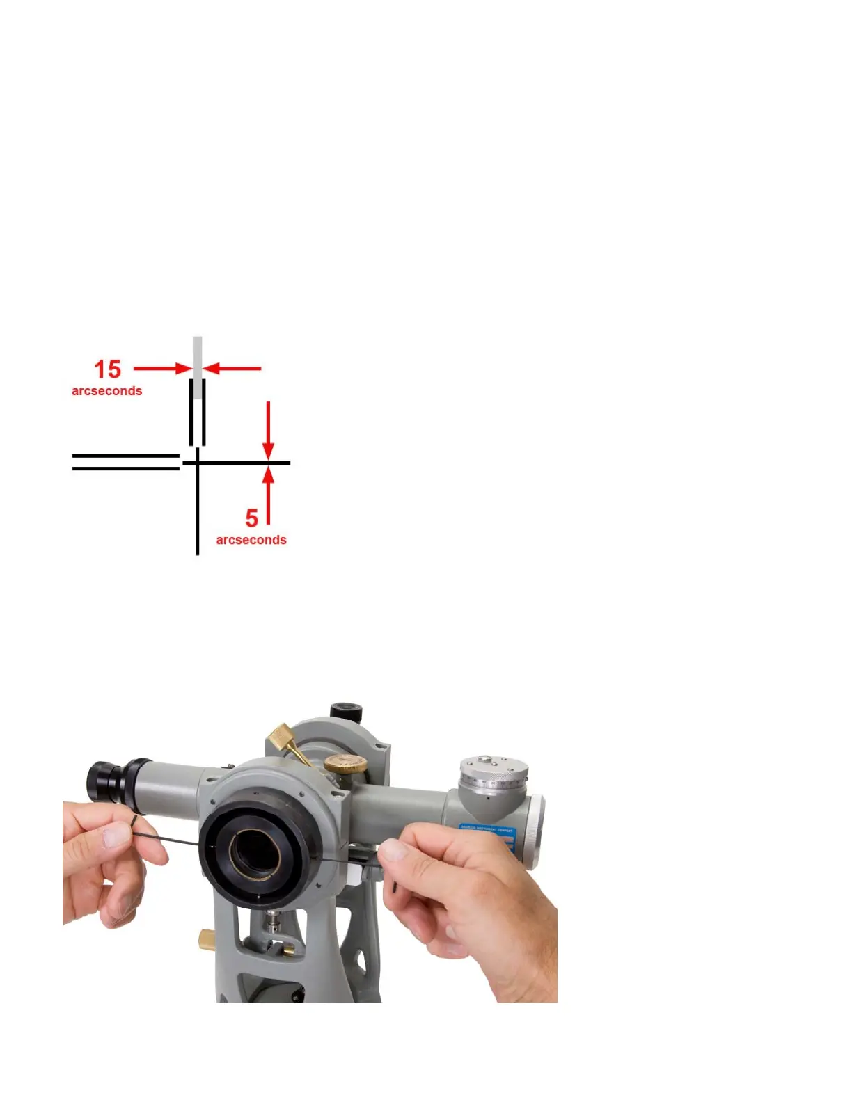
7.Iftheobservederrorexceeds2arcseconds,adjustmentisre‐
quired.Removetheflangecoverfromtheobjectiveendofthecross
‐axistelescopesimplybypullingitstraightoff(it’safrictionfit).
Thenmovethesocketheadset‐screwsinthecross‐axistelescope
objectivelensmounting
flangetophysicallypush
thelensfromsidetosideto
correctthiserror.Asyou’d
expect,usethehorizontally
opposedadjustmentscrews
toshifttheimagehorizon‐
tally,andtheverticallyori‐
entedscrewstoshifttheim‐
agevertically(Figure4.8).
Rememberthat
youshould
removeonlyhalfoftheap‐
parenterror.
8.Repeatsteps5through7
untiltheerrorobservedis
withintheallowabletoler‐
ance.
Figure4.8
Figure4.7