APPLICATION DATA
1. Ductwork must be attached to the curb on all units. Interior
installation may proceed before unit is set in place on roof.
Field-fabricated concentric ductwork may be connected as
shown below.
2. Factory- and field-installed electric heat allows single power
entry to unit for both heating and cooling. Values shown for
minimum circuit amps (MCA) and maximum overcurrent
protection (MOCP) in the Electrical Data table on page 11
apply to factory- or field-installed heaters.
3. Indoor coil is draw-thru configuration. Condensate trap
(minimum 4 in. deep) must be field-installed prior to start-up
on cooling cycle. Install plug in condensate drain on oppo-
site side of unit from trap.
4. When return-air ductwork systems are used, return hori-
zontal static pressures should be limited to 0.4 in. wg.
5. Cfm and other values indicated throughout this literature il-
lustrate the operating range of the equipment. Operation
outside these limits is not recommended.
6. When use is required with emergency heat, in addition to
accessory emergency-heat components, field-supplied
emergency heat switch (DPST toggle switch) must be
used. Emergency heat subbase cannot be used with the re-
mote control panel.
7. Units are designed to operate at outdoor temperatures
down to 40 F. At temperatures below 40 F, accessory head
pressure control device will permit operation at outdoor
temperatures as low as −20 F.
8. All roof curb and adapter installations must be counter-
flashed to prevent water leakage.
9. Select unit based on cooling only. Do not select heat pumps
on heating capacity. Add auxiliary resistance heat if
required.
10. Electric power may be brought to unit within curb perimeter
through fittings provided in basepan. Provide power supply
in accordance with local codes. Branch circuit protection to
unit must be provided by fuses no larger than MOCP shown
in Electrical Data table on page 11.
11. The 24-v control wiring to thermostat is NEC (National Elec-
trical Code) Class II.
OPTIONS AND ACCESSORIES
ITEM OPTION* ACCESSORY†
Alternate Drive X
Integrated Economizer XX
Electric Heater X
Emergency Heat Package X
Roof Curb (Vertical and Horizontal) X
Horizontal Adapter X
Remote Control Panel X
Thermostats and Subbases X
Time GuardT Control Device X
Power Exhaust X
Two-Position Damper X
Barometric Relief Damper X
Head Pressure Control X
*Factory Installed.
†Field Installed.
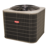
Concentric Duct Air Distribution
NOTE: Do not drill in this area, damage to basepan may result in
water leak.
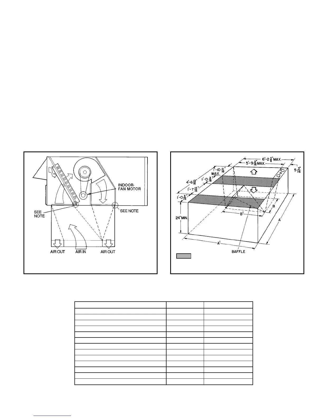
Concentric Duct Details
Shaded area indicates block-off panels.
NOTE: Dimensions A, A8 and B, B8 are obtained from field-
supplied ceiling diffuser.
13