LEGEND FOR TYPICAL FIELD WIRING
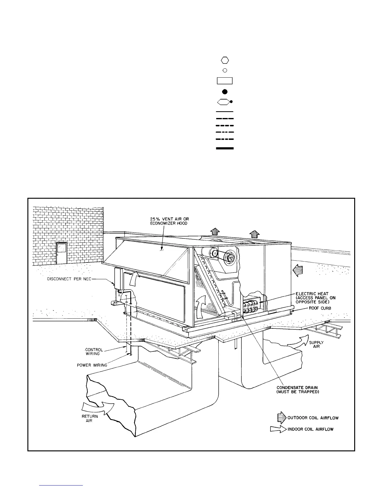
TYPICAL INSTALLATION
AHA — Adjustable Heat Anticipator
BKR W/AT — Breaks With Amp Turns
C—Contactor
CB — Circuit Breaker
CC — Cooling Compensator
CLO — Cooling Lockout
CLS — Cooling Lockout Switch
CR — Control Relay
CT — Current Transformer
DFR — Defrost Relay
DM — Damper Motor
DR — Damper Relay
EC — Enthalpy Control
FPT — Freeze Protection Thermostat
HC — Heater Contactor
HPS — High-Pressure Switch
HR — Heater Relay
IFC — Indoor Fan Contactor
IP — Internal Protector
L—Light
LOR — Lockout Relay
LPS — Low-Pressure Switch
MAT — Mixed Air Thermostat
PL — Plug Assembly
PRI — Primary
RVR — Reversing Valve Relay
SW — Switch
TB — Terminal Block
TC — Thermostat, Cooling
TH — Thermostat, Heating
TRAN — Transformer
Terminal (Marked)
Terminal (Unmarked)
Terminal Block
Splice
Splice (Marked)
Factory Wiring
Field Control Wiring
Field Power Wiring
Accessory Wiring or Optional Wiring
Accessory
To indicate common potential only;
Not to represent wiring.
NEC — National Electrical Code
15