Table 7 — Accessory/FIOP Static Pressure (in. wg)
ACCESSORY/FIOP UNIT SIZE UNIT VOLTAGE kW
CFM
3750 4000 4500 5000 5600 6000 6250 7200 7500
Electric Heaters
150
208/230-3-60
14-34
42,56
0.05
0.06
0.05
0.06
0.06
0.07
0.07
0.08
0.08
0.10
0.09
0.12
0.09
0.13
††
460-3-60
15,32
55
0.05
0.06
0.05
0.06
0.06
0.07
0.07
0.08
0.08
0.10
0.09
0.12
0.09
0.13
††
180
208/230-3-60
26,34
42,56
****
0.10
0.08
0.09
0.12
0.09
0.13
0.11
0.16
0.12
0.17
460-3-60
32
55
****
0.10
0.13
0.09
0.12
0.09
0.13
0.11
0.15
0.12
0.17
Economizer All All — 0.03 0.03 0.04 0.05 0.06 0.07 0.07 0.09 0.10
Glycol Coil All All — 0.16 0.18 0.22 0.26 0.31 0.35 0.37 0.44 0.46
LEGEND
FIOP — Factory-Installed Option
*Do not operate unit with electric heat at this cfm. Operation at this cfm
is below electric heat required minimum cfm.
†Do not operate unit at this cfm. Operation at this cfm is above unit
maximum cfm limit.
NOTES:
1. Heaters are rated at 208/240 v and 480 v.
2. The factory assembled horizontal adapter substantially improves fan
performance. See Fig. 23.
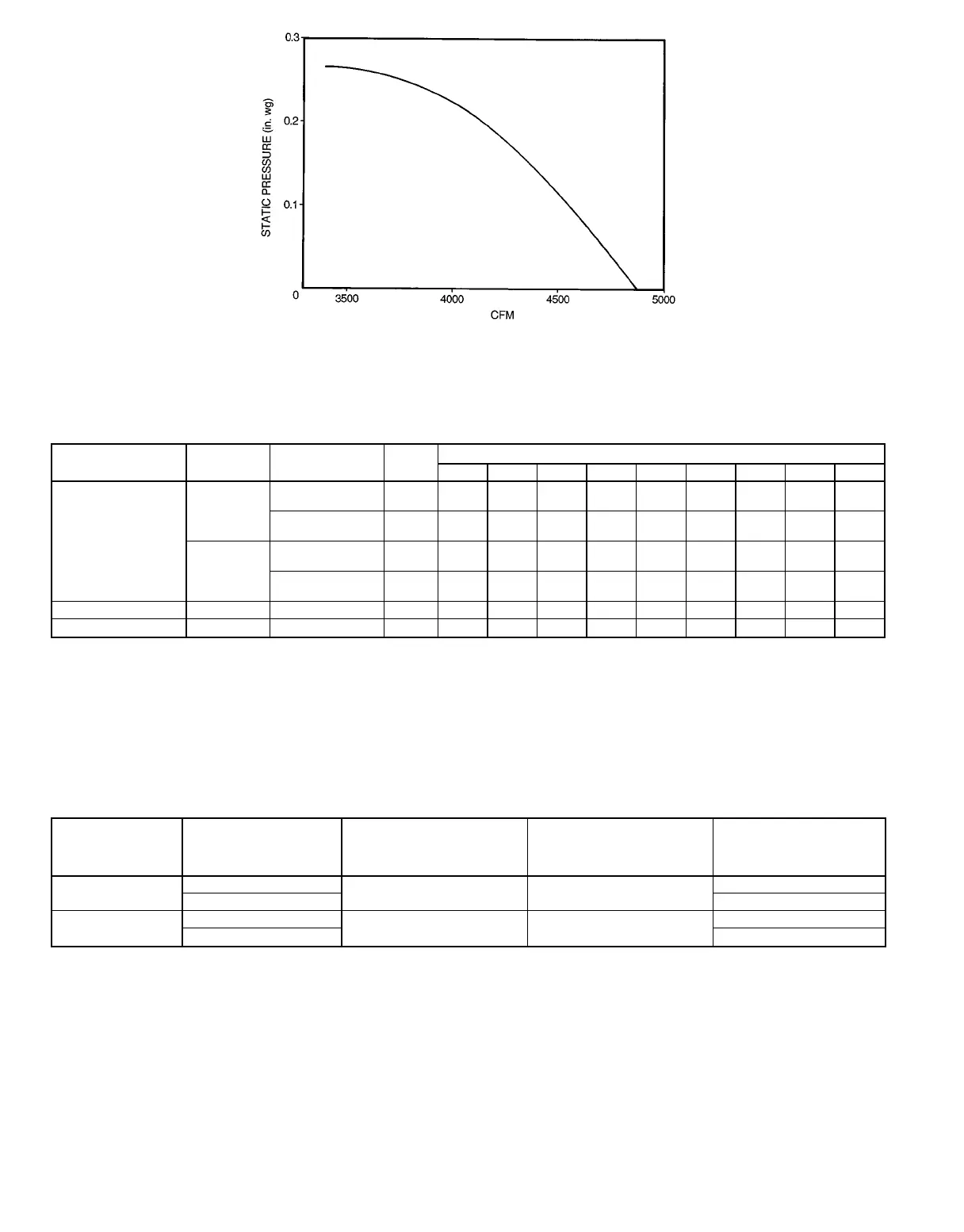
3. The static pressure must be added to external static pressure. The
sum and the indoor-air section entering-air cfm should then be used
in conjunction with the Tables 5 and 6 to determine blower rpm, bhp,
and watts.
Table 8 — Indoor-Fan Motor Performance
UNIT
542J
UNIT
VOLTAGE
MAXIMUM
ACCEPTABLE
CONTINUOUS
BHP*
MAXIMUM
ACCEPTABLE
OPERATING
WATTS
MAXIMUM
AMP DRAW
150
208/230
4.25 3775
10.5
460 4.8
180
208/230
5.90 5180
15.8
460 7.9
LEGEND
Bhp — Brake Horsepower
*Extensive motor and electrical testing on these units ensures that the
full horsepower range of the motors can be utilized with confidence.
Using your fan motors up to the horsepower ratings shown in this table
will not result in nuisance tripping or premature motor failure. Unit war-
ranty will not be affected.
Fig. 24 — Fan Performance Using Accessory Power Exhaust
—18—
 Loading...