—25—
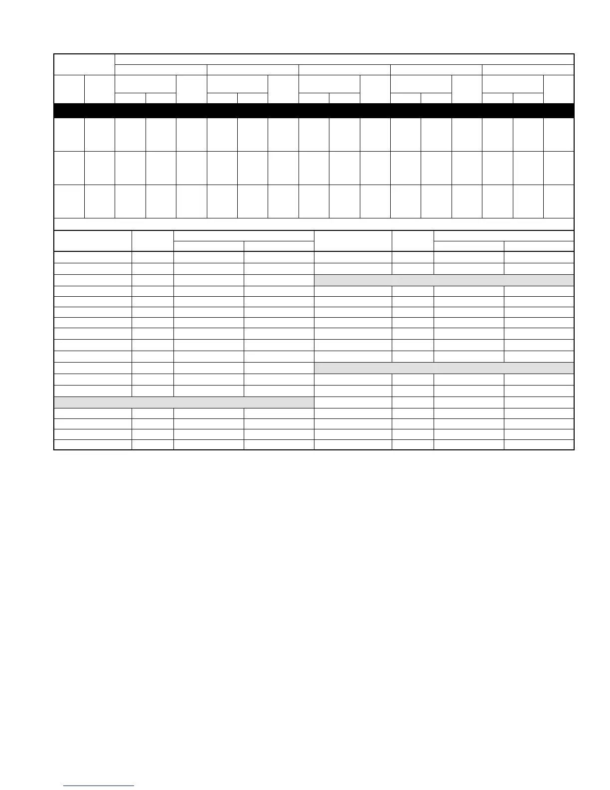
DETAILED COOLING CAPACITIES* Continued
NOTE: When the required data fall between the published data, interpolation may be performed. Extrapolation is not an acceptable practice.
* Detailed cooling capacities are based on indoor and outdoor unit at the same elevation per ARI standard 210/240-94. If additional tubing length and/or
indoor unit is located above outdoor unit, a slight variation in capacity may occur.
† Total and sensible capacities are net capacities. Blower motor heat has been subtracted.
‡ Sensible capacities shown are based on 80°F (27°C) entering air at the indoor coil. For sensible capacities at other than 80°F (27°C), deduct 835 Btuh (245
kW) per 1000 CFM (480 L/S) of indoor coil air for each degree below 80°F (27°C), or add 835 Btuh (245 kW) per 1000 CFM (480 L/S) of indoor coil air per
degree above 80°F (27°C). When the required data falls between the published data, interpolation may be performed.
** Unit kW is total of indoor and outdoor unit kilowatts.
EVAPORATOR
AIR
CONDENSER ENTERING AIR TEMPERATURES °F
85 95 105 115 125
CFM EWB
Capacity
MBtuh†
Total
System
kW**
Capacity
MBtuh†
Total
System
kW**
Capacity
MBtuh†
Total
System
kW**
Capacity
MBtuh†
Total
System
kW**
Capacity
MBtuh†
Total
System
kW**Total Sens‡ Total Sens‡ Total Sens‡ Total Sens‡ Total Sens‡
597CN060-F, G Outdoor Section With CC5A/CD5AW060 Indoor Section
1750
72 63.6 31.1 4.98 61.2 30.3 5.51 58.7 29.3 6.08 56.1 28.4 6.71 53.5 27.4 7.41
67 58.2 39.2 4.90 56.0 38.3 5.42 53.7 37.4 5.99 51.3 36.4 6.62 48.9 35.4 7.31
62 53.1 47.1 4.83 51.0 46.1 5.34 48.9 45.1 5.90 46.8 44.0 6.53 44.6 42.8 7.21
57 50.4 50.4 4.80 48.8 48.8 5.31 47.2 47.2 5.88 45.5 45.5 6.50 43.7 43.7 7.19
2000
72 64.8 32.5 5.09 62.3 31.6 5.62 59.7 30.6 6.20 57.0 29.7 6.84 54.2 28.6 7.50
67 59.3 41.5 5.01 57.0 40.6 5.53 54.6 39.6 6.11 52.1 38.6 6.73 49.6 37.6 7.43
62 54.2 50.2 4.94 52.0 49.1 5.46 49.8 47.9 6.02 47.6 46.6 6.65 45.4 45.1 7.34
57 52.3 52.3 4.92 50.6 50.6 5.43 48.8 48.8 6.00 47.0 47.0 6.62 45.2 45.2 7.32
2250
72 65.7 33.7 5.20 63.1 32.8 5.73 60.4 31.8 6.31 57.7 30.9 6.94 54.6 29.8 7.60
67 60.2 43.7 5.12 57.8 42.8 5.64 55.3 41.8 6.22 52.8 40.8 6.84 50.2 39.8 7.54
62 55.0 52.9 5.05 52.8 51.6 5.57 50.6 50.2 6.14 48.5 48.5 6.76 46.4 46.4 7.45
57 54.0 54.0 5.03 52.2 52.2 5.55 50.3 50.3 6.12 48.4 48.4 6.75 46.4 46.4 7.45
Multipliers for Determining the Performance With Other Indoor Sections
Indoor
Section Size
Cooling
Indoor
Section Size
Cooling
Capacity Power Capacity Power
CC5A/CD5AW 060 1.00 1.00
CK5A/CK5BT 060 0.96 0.93
CC5A/CD5AA 060 0.96 0.97
CK5A/CK5BX 060 0.98 0.93
CE3AA 060 1.00 1.00
COILS + 315(A,J)AV066135 VARIABLE SPEED FURNACE
CK3BA 060 0.96 1.00 CC5A/CD5AA 060 0.96 0.95
CK5A/CK5BA 060 0.96 0.98 CC5A/CD5AW 060 0.98 0.95
CK5A/CK5BN 060 0.96 0.98 CE3AA 060 0.96 0.92
CK5A/CK5BX 060 1.00 1.00 CK3BA 060 0.96 0.94
F(A,B)4(A,B)N(F,B) 060 1.00 1.04
CK5A/CK5BA 060 0.96 0.94
FB4(A,B)NB 070 1.02 1.02
CK5A/CK5BT 060 0.96 0.94
FC4(B,C)N(F,B) 060 1.00 1.04
CK5A/CK5BX 060 0.98 0.93
FC4(B,C)NB 070 1.02 1.02
COILS + 315(A,J)AV066155 VARIABLE SPEED FURNACE
FG3AAA 060 1.00 1.00
CC5A/CD5AA 060 0.96 0.94
FK4(C,D)NB 006 1.02 1.00
CC5A/CD5AW 060 0.98 0.94
COILS + 315(A,J)AV066110 VARIABLE SPEED FURNACE
CE3AA 060 0.96 0.91
CC5A/CD5AA 060 0.96 0.95 CK3BA 060 0.96 0.93
CE3AA 060 0.96 0.92 CK5A/CK5BA 060 0.96 0.93
CK3BA 060 0.96 0.93 CK5A/CK5BT 060 0.96 0.93
CK5A/CK5BA 060 0.96 0.93 CK5A/CK5BX 060 0.98 0.92
SYSTEM DESIGN SUMMARY
1. Intended for outdoor installation with free air inlet and outlet. Outdoor fan external static pressure available is less than 0.01-in. wc.
2. Minimum outdoor operating air temperature without low-ambient operation accessory is 55°F (12.8°C).
3. Maximum outdoor operating air temperature is 125°F (51.7°C).
4. For reliable operation, unit should be level in all horizontal planes.
5. Maximum elevation of indoor coil above or below base of outdoor unit is: Indoor coil above = 50 ft, indoor coil below = 150 ft.
6. For interconnecting refrigerant tube lengths between 50 and 175 ft or 20 ft vertical differential, consult the Residential Split System Long-Line
Application Guideline available from equipment distributor.
7. If any refrigerant tubing is buried, provide a minimum 6-in. vertical rise to the valve connections at the unit. Refrigerant tubing lengths up to 36 in.
may be buried without further consideration. For buried lines longer than 3 ft, consult your local distributor.
8. Use only copper wire for electric connection at unit. Aluminum and clad aluminum are not acceptable for the type of connector provided.
9. Mismatches of indoor coil capacity more than 1 size larger than outdoor unit capacity may result in inadequate indoor comfort.
10. Do not apply capillary tube indoor coils to these units.
 Loading...