—5—
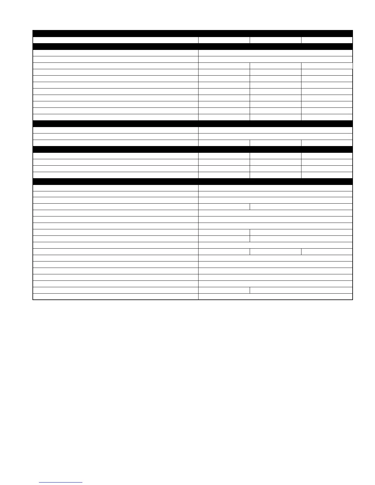
SPECIFICATIONS Continued
*Permissible limits of the voltage range at which the unit will operate satisfactorily. Operation outside these limits may result in unit failure.
† If other than uncoated (non-plated), 60°C or 75°C (140° or 167°F) insulation, copper wire (solid wire for 10 AWG and smaller, stranded wire for larger than
10 AWG) is used, consult applicable tables of the NEC (ANSI/NFPA 70).
If wire is applied at ambient greater than 30°C (86°F), consult Table 310-16 of the NEC (ANSI/NFPA 70). The ampacity of nonmetallic-sheathed cable
(NM), trade name ROMEX, shall be that of 60°C (140°F) conductors, per the NEC (ANSI/NFPA 70) Article 336-26.
‡ Length shown is as measured 1 way along the wire path between the unit and the service panel for a voltage drop not to exceed 2 percent.
** Time-delay fuse or circuit breaker.
†† The factory refrigerant charge is for 15 ft of interconnecting tubing. For tubing lengths other than 15 ft, refer to the Residential Split-Systems Long-Line
Application Guideline and Service Manual for Residential Split-System Air Conditioners and Heat Pumps using Puron (R-410A).
‡‡ Install with Ball-Bearing Fan Motor.
*** Use with low-ambient pressure switch.
NOTE:
Copper wire must be used from service disconnect to unit. All motors/compressors contain internal overload protection.
UNIT SIZE-SERIES 042-D, E 048-D, E, F 060-D, E
Operating Weight (Lb) 218 266 295
ELECTRICAL
Unit Volts—Hertz—Phase 208/230—60—1
Operating Voltage Range* 187—253
Compressor Rated Load Amps 21.1 20.5/21.8 27.6
Compressor Locked Rotor Amps 104.0 109.0/117.0 158.0
Condenser Fan Motor—Full Load Amps 1.1 1.4 1.4
Minimum Unit Ampacity for Wire Sizing 27.5 27.0/28.6 35.9
Minimum Wire Size (60°C Copper) (AWG)† 10 10 8
Minimum Wire Size (75°C Copper) (AWG)† 10 10 8
Maximum Wire Length (60°C) (Ft)‡ 71 74/69 86
Maximum Wire Length (75°C) (Ft)‡ 68 70/66 82
Maximum Branch Circuit Fuse Size** 40 40 60
COMPRESSOR & REFRIGERANT
Compressor Type Scroll
Refrigerant Type Puron
Refrigerant Amount (Lb)†† 8.63 13.25 13.25
OUTDOOR COIL & FAN
Coil Face Area (Sq Ft) 12.12 18.18 18.18
Fins per In.—Rows—Circuits 20—2—3 20—2—4 20—2—5
Fan Motor—HP & RPM 1/5 and 825 1/4 and 1100 1/4 and 1100
Rated Airflow (CFM) 2800 3300 3300
OPTIONAL EQUIPMENT
Support Feet—4 In. (4) KSASF0101AAA
Snow Stand—18 In. KHASS0206MPK
Time Delay Relay KAATD0101TDR
Ball-Bearing Fan Motor HC38GE231 HC40GE232
MotorMaster®—Low-Ambient Controller‡‡ KSALA0401AAA
Outdoor Thermostat KHAOT0301FST
Secondary Outdoor Thermostat KHAOT0201SEC
Crankcase Heater KAACH1201AAA Standard
Start Assist—Capacitor/Relay Type KSAHS1501AAA KSAHS1601AAA
Start Assist—PTC Type KAACS0201PTC
Bi-Flow TXV (Hard Shutoff) KSATX0301PUR KSATX0401PUR KSATX0501PUR
Evaporator Freeze Thermostatz*** KAAFT0101AAA
Isolation Relay*** KHAIR0101AAA
Liquid-Line Solenoid Valve (LSV) KHALS0401LLS
Low-Ambient Pressure Switch KSALA0301410
Coastal Filter KAACF0801MED
Pressure Guard™ Kit KHAPG0101PGS KHAPG0201PGS
Evolution Controls See chart.