191VAN Evolution™ Extreme Variable Speed Air Conditioner: Installation Instructions
Manufacturer reserves the right to change, at any time, specifications and designs without notice and without obligations.
11
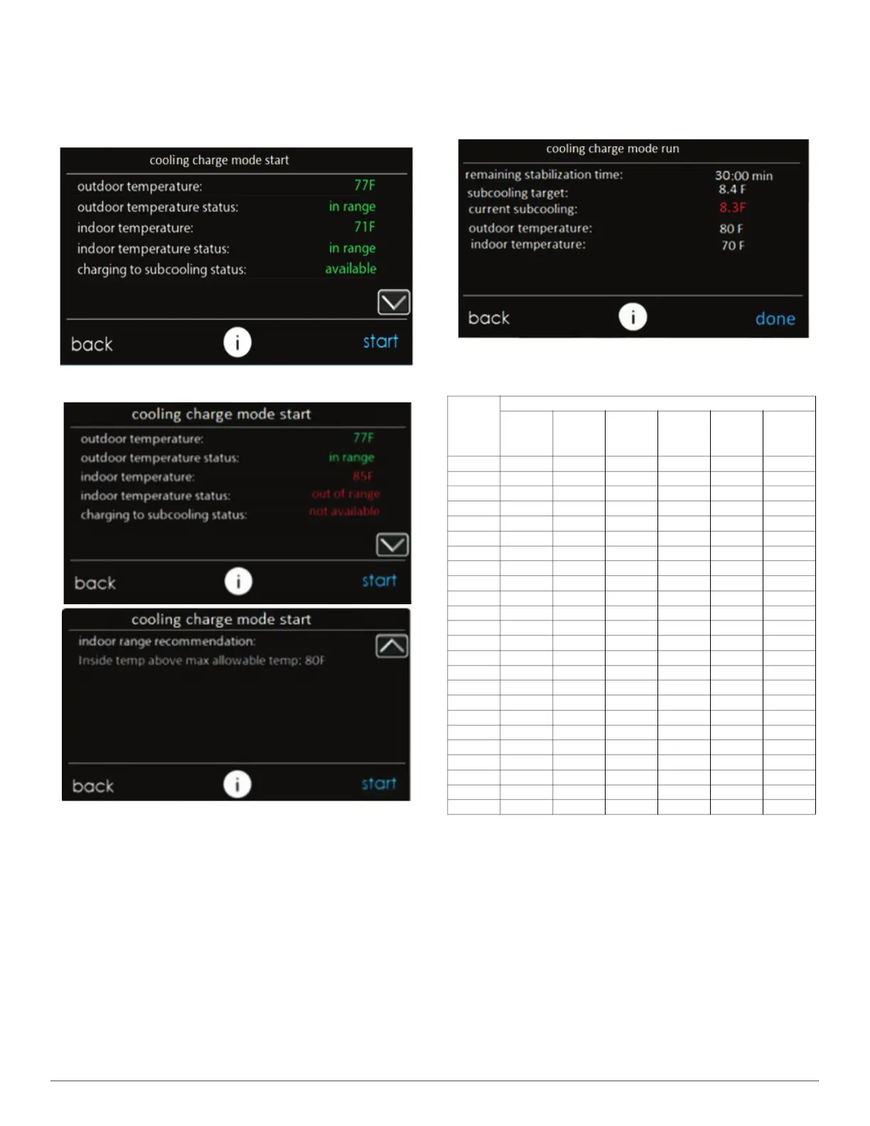
8. The next screen, “cooling charge mode start” is shown in Fig. 17 or
Fig. 18 depending on whether subcooling charging is available. The
reason for unavailability of subcooling can be viewed by pressing
the down arrow to go to the second page. Before selecting “Start”,
verify that the service valves are open. Pressing start will turn on
the system at a fixed set of operating parameters in COOLING
mode.
A240373
Fig. 17 – Cooling Charge Mode Start Screen - Subcooling Available
A240385
Fig. 18 – Cooling Charge Mode Start Screen - Subcooling
Unavailable
9. Once start has been pressed, the next screen will show the target
subcooling that should be attained while charging. If subcooling
mode is not available, the current subcooling and target will display
as dashes and the refrigerant must be weighed in. Weigh in the
charge amount recorded in Step 7. The charge level may then be
checked at another time when both the indoor and outdoor
temperatures are in a more favorable range that allow for
subcooling charging.
When subcooling is available, the current subcooling will appear in
red (Fig. 19) until the stabilization timer is 0 where it will then turn
green, indicating the system has stabilized. "Current subcooling" is
calculated using sensors inside the ODU, but may be in error until
stabilization time has completed. Compare the "current subcooling"
to the “subcooling target” listed on the charging screen. Add
refrigerant if the subcooling is low and remove refrigerant if
subcooling is high. Tolerance should be ±1°F. It is recommended to
validate the subcooling using traditional methods of measuring
temperature and pressure at the liquid service valve when charging
the system.Refer to Table 4 for guidance on required liquid line
temperature for a given subcooling and liquid service valve
pressure.
A240375
Fig. 19 – Cooling Charge Mode Run Screen
10. If any adjustment is necessary, add or remove the charge slowly (no
greater than 0.5 lb per minute) and allow system to operate for at
least 15 minutes to stabilize before declaring a properly charged
system. The use of a commercial charge metering device (restrictor)
such as Imperial liquid low side charger model 535-C or Watsco
ChargeFaster model CH200 is recommended when adding
refrigerant to an operating system. This prevents potential damage
of liquid slugging of the compressor and allows the subcooling to
stabilize quicker.
11. If the lineset is less than 15 ft. (4.57 m) in length, charge removal
may be necessary and will be shown as a negative number on
Evolution™ Connex™ System Control screen. Note that the
IEvolution™ Connex™ System Control screen displays charge in
lb and oz, while unit rating plate is in decimal format.
Table 4 – Required Liquid Line Temperature for R-454B
Liquid
(PSIG)
Pressure
at Service
Valve
R-454B Subcooling Temperature (F)
6 8 10 12 14 16
238 78 76 74 72 70 68
245 80 78 76 74 72 70
252 82 80 78 76 74 72
260 84 82 80 78 76 74
268 86 84 82 80 78 76
276 88 86 84 82 80 78
284 90 88 86 84 82 80
292 92 90 88 86 84 82
301 94 92 90 88 86 84
309 96 94 92 90 88 86
318 98 96 94 92 90 88
327 100 98 96 94 92 90
336 102 100 98 96 94 92
346 104 102 100 98 96 94
355 106 104 102 100 98 96
365 108 106 104 102 100 98
375 110 108 106 104 102 100
385 112 110 108 106 104 102
396 114 112 110 108 106 104
406 116 114 112 110 108 106
417 118 116 114 112 110 108
428 120 118 116 114 112 110
439 122 120 118 116 114 112
450 124 122 120 118 116 114