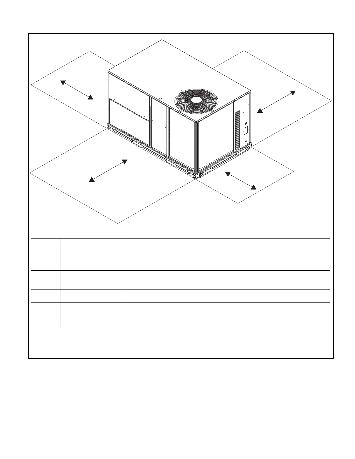
NOTE: Unit not designed to have overhead obstruction. Contact Application Engineering for guidance on any application plan-
ning overhead obstruction or for vertical clearances.
SERVICE CLEARANCE DIMENSIONS
LOCATION DIMENSION CONDITION
A
48-in. (1219 mm) Unit disconnect is mounted on panel
18-in. (457 mm) No disconnect, convenience outlet option
18-in. (457 mm) Recommended service clearance
12-in. (305 mm) Minimum clearance
B
42-in. (1067 mm) Surface behind servicer is grounded (e.g., metal, masonry wall)
36-in. (914 mm) Surface behind servicer is electrically non-conductive (e.g., wood, fiberglass)
Special Check sources of flue products within 10 ft (3 m) of unit fresh air intake hood
C
36-in. (914 mm) Side condensate drain is used
18-in. (457 mm) Minimum clearance
D
48-in. (1219 mm) No flue discharge accessory installed, surface is combustible material
42-in. (1067 mm) Surface behind servicer is grounded (e.g., metal, masonry wall, another unit)
36-in. (914 mm) Surface behind servicer is electrically non-conductive (e.g., wood, fiberglass)
Special Check for adjacent units or building fresh air intakes within 10 ft (3 m) of this unit’s flue outlet
 Loading...


