6.1 Layout of the operating and display elements
1
2
3
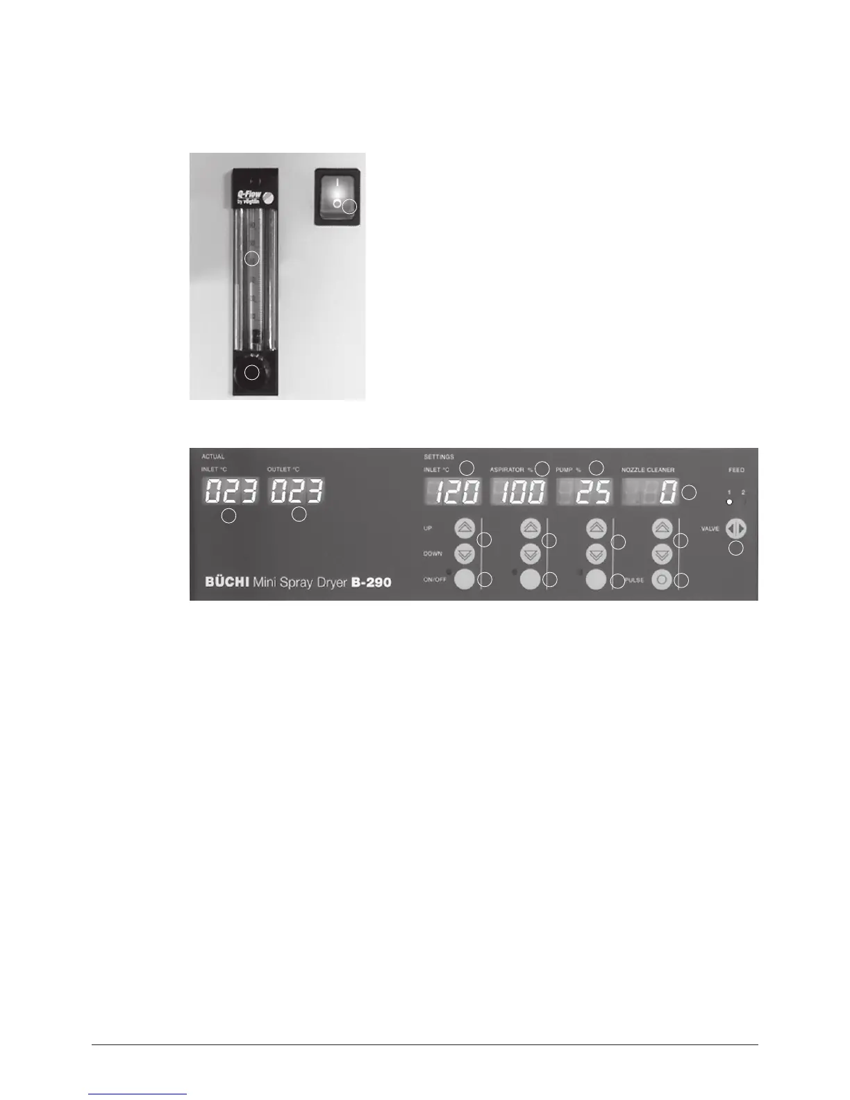
a Main switch
b Flow meter for spraying gas volume
c Needle valve for gas flow adjustment
Fig. 6.1: Switch, flow meter and valve
2
3
4
1
6
7
8
13
9
10
11
12
5
14
15
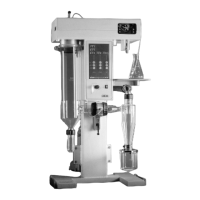
a LED display current value inlet air temperature
b LED display current value outlet air temperature
c LED display set value inlet air temperature
d LED display aspirator output in % of max. aspirator rate
e LED display pump output in % of max. pump rate
f LED display for nozzle cleaning
g Feed switch valve button
h Nozzle cleaner interval adjustment
i Manual operation pneumatic nozzle cleaner
j Regulating push-button pump
k Main switch pump
l Regulating push-button aspirator
m Main switch aspirator
n Regulating push-button heating
o Main switch heating
Fig. 6.2: Operating and display elements