5 Putting into operation
19 Pump Combinations Operation Manual, Version E
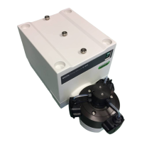
Pressure tubing 1/8” x 1/16”:
1
5
2
Cut the pressure tubing to the desired length. Attach
the fitting b and the ferrules to one end of the tubing
a as described.
Screw the fitting b into the upper output e of
the separator head. Make sure that all fittings are
hand-tight.
Fig. 5.3: Pump head with connected pressure tubing
5.3.2 Pump system 1: Pump Controller C-610 and 1 Pump Module C-601
NOTE
The Pump Controller C-610 can only be connected to the Pump Module C-601.
1
2
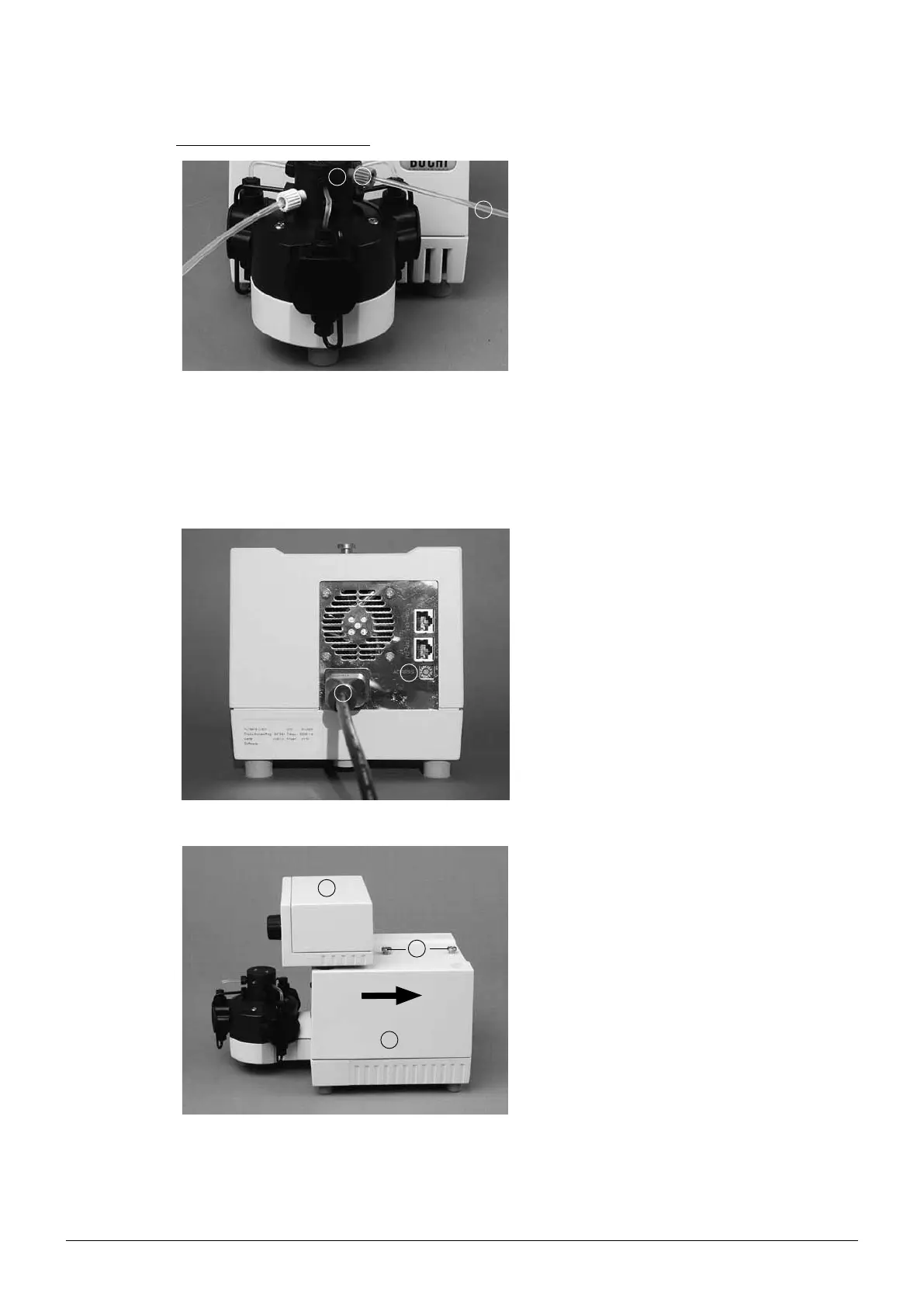
Place the pump module on a level surface. Make
sure the address bus is set to A b. If not, take the
screwdriver and turn the small white dot to A. Con-
nect the power cord a.
Fig. 5.4: Rear connections of the pump module
1
2
3
A holding angle is located in the center at the back
of the pump controller a. Remove it.
There is a rail located at the bottom of the pump
controller a. Slide it from the front to the end of the
stop b on the pump module c.
Attach the holding angle.
Fig. 5.5: Installing the pump controller and the pump module