Content
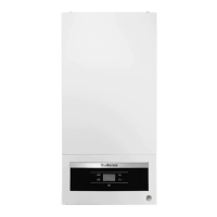
GB012 - 25K
2
Content
1 Safety precautions and symbols . . . . . . . . . . . . . . . 3
1.1 Symbols . . . . . . . . . . . . . . . . . . . . . . . . . . . . . 3
1.2 Safety precautions . . . . . . . . . . . . . . . . . . . . . 3
2 Service Functions . . . . . . . . . . . . . . . . . . . . . . . . . . . 4
2.1 Display Symbols . . . . . . . . . . . . . . . . . . . . . . . 4
2.2 Service Function . . . . . . . . . . . . . . . . . . . . . . 4
2.3 Service Function Overview . . . . . . . . . . . . . . 5
2.3.1 1. Service Level . . . . . . . . . . . . . . . . . . . . . . . 5
2.3.2 2. Service Level . . . . . . . . . . . . . . . . . . . . . . . 6
3 Failures / Errors . . . . . . . . . . . . . . . . . . . . . . . . . . . . . 7
3.1 Elimination of errrors . . . . . . . . . . . . . . . . . . . 7
3.2 Failure / Error Codes Overview . . . . . . . . . . . 8
3.3 Failure codes and corrections steps . . . . . . . 9
3.4 Sensor (NTC) Values . . . . . . . . . . . . . . . . . . 25
3.4.1 Flow Temperature Sensor . . . . . . . . . . . . . . 25
3.4.2 Domestic Hot Water Temperature Sensor . . 25
3.4.3 Flue Gas Safety Temperature Sensor (Behind
Burner) . . . . . . . . . . . . . . . . . . . . . . . . . . . . 25
3.5 Electrical Datas . . . . . . . . . . . . . . . . . . . . . . 26
3.6 Electrical Circuit Diagram . . . . . . . . . . . . . . . 27
3.7 Structure . . . . . . . . . . . . . . . . . . . . . . . . . . . . 29
3.8 Function Diagram . . . . . . . . . . . . . . . . . . . . . 31
4 Gas Values (Cental heating and domestic
hot water circuit) 32