3
Installation
MCM10
10
3 Installation
3.1 Installation
3.1.1 Wall mounting
B Determine the location on the wall in accordance with
the dimensions of the MCM10 module.
B Determine whether the main power cord is laid in stiff
or flexible ducts that require duct connection box and
appropriate free space under the MCM10.
B Undo two screws at the bottom of the MCM10 module,
pull the cover at the bottom forward and lift off upwards
(Æ Fig. 6).
Fig. 6 Removing the cover
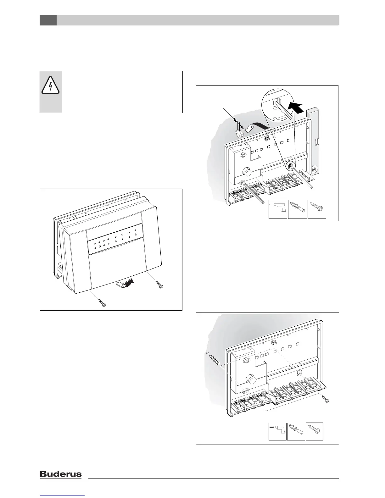
B For the upper attachment screw, drill a Ø 1/4" (6 mm)
hole, insert an appropriate wall anchor, and insert the
screw until only 1/16" (1.5 mm) protrudes (Æ Fig. 7).
Fig. 7 Upper attachment screw
B In the back panel of the MCM10 module, create two
holes for the lower attachment screws using the
breakouts prepared.
B Attach the MCM10 module at the top attachment
screw.
B Mark the holes to be drilled on the wall through the
breakouts created.
B Remove the MCM10 module.
B Drill Ø 1/4" (6 mm) holes and insert wall anchors
(Æ Fig. 8).
Fig. 8 Insert wall anchor
DANGER: Risk of electric shock!
B Before connecting the power supply,
interrupt the power supply to the heating
appliances and to all other BUS
subscribers.
7 746 800 090-03.1O
1/4"
3,5 mm
0.05" (1,5mm)
6 720 617 648-02.1O
3.
4.
4.
2.
1.
1/4"
1/4"
3,5 mm
6 720 617 648-03.1O
1/4"
1/4"

 Loading...


