5
Operating and fault indications
MCM10
16
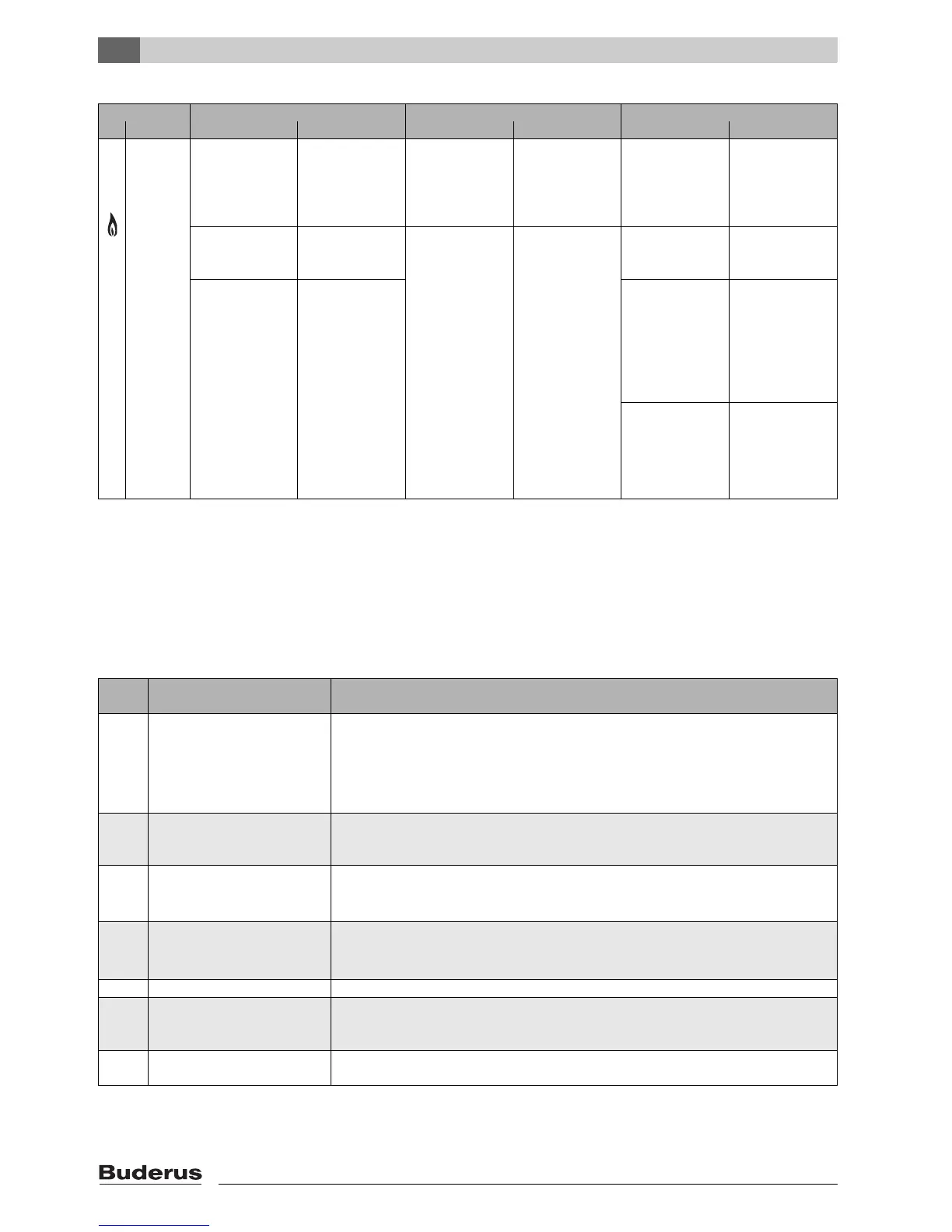
5.4 Operating and fault indications via
the RC35
The operating and fault indications of all heating
appliances and the MCM10 module can be checked on
the heating controller with 2-wire BUS control. The
meaning of the display indications of the MCM10 are
described in table 10. The meaning of the other display
indications are described in the documentation for the
controller and the boiler.
5,
6,
7,
8
Heating
appliance 1
heating
appliance 2
heating
appliance 3
heating
appliance 4
Operation: No heat
demand to the heat-
ing appliance; heat-
ing appliance
operational
– Operation: Heat
demand to the heat-
ing appliance; heat-
ing appliance in
operation
– Configuration:
Communication
between this heat-
ing appliance and
the MCM10 module.
Wait until the con-
figuration has com-
pleted.
Operation: No
heating appliance
connected
– Fault: Heating
appliance fault
Remove fault on the
heating appliance.
Configuration/
Fault: No communi-
cation between the
MCM10 module
and this heating
appliance, although
it is installed.
Check the corre-
sponding connec-
tion cable.
Remove fault on the
heating appliance.
Replace MCM10
module.
Fault: No communi-
cation between the
MCM10 module
and this heating
appliance because it
has been deliber-
ately removed.
Reset the configura-
tion
(Æ paragrahp 4.3).
Fault: Communica-
tion error between
the MCM10 mod-
ule and heating
appliance.
1)
Check the corre-
sponding connec-
tion cable.
Replace MCM10
module.
1) Another heating appliance will be enabled automatically in case of heat demand.
LED OFF ON Flashing
No. Function Diagnosis Remedy Diagnosis Remedy Diagnosis Remedy
Tab. 9 Operating and fault indications on the MCM10 module
Indica-
tor
Description Remedy
5H Break in BUS communication • Display with fewer than 4 heating appliances.
• Check connecting cable between the boiler and the MCM10 module for cable breaks.
• Check whether the cable makes good contact.
• Check whether this fault originates from a boiler (Æboiler installation instructions).
• Replace MCM10 module.
4U
4Y
The contacts for the supply sensor
have been interrupted (4Y) or have
shorted (4U).
• Check supply temperature sensor and connecting lead.
• Replace MCM10 module.
EF Internal electronic fault • If the fault is indicated as being applicable to one of the boilers: Replace the PCB on the relevant
boiler.
• If the fault is not indicated as attributable to one of the boilers: Replace the MCM10 module.
8Y The external switch contact is open. • Check the cable of the external switching contact for cable breaks.
• Check whether the connection plug is present.
• Replace MCM10 module.
AE Jumper configuration error. • Check whether the jumper is attached correctly.
AU The calculated boiler water temper-
ature is not achieved in timely fash-
ion.
• Check whether enough heating appliances are working.
AY An error has occurred on one or
more heating appliances.
• Eliminate the error on the corresponding boiler.
Tab. 10 Operating and fault indications via the RC35

 Loading...


