3
Installation
MCM10
12
B Recommendation when using several MCM10
modules (cascade with more than four heating
appliances): Provide the additional modules with
power via the first MCM10 module (master). This
ensures simultaneous start-up.
3.2.3 Connection of a remote fault indication with
optical and acoustic signal
For example, a fault indicator can be connected to the
zero volt fault contact (Æ Fig. 12, terminal D, page 19).
The state of the fault contact is also indicated via an LED
on the MCM10 (Æ Tab. 9, page 14).
This is a dry contact that carries a maximum current of 2 A
at 120 V AC.
3.2.4 Electrical connection of the outdoor
temperature sensor
In conjunction with heating system controls with 2-wire
BUS control, always connect outdoor temperature sensor
to the MCM10 module (master) (Æ Fig. 12, page 19) and
not to the heating appliance.
3.2.5 Electrical connection of the supply
temperature sensor
For system version 1, the common supply temperature
sensor must be connected to the WM10 (Æ installation
instructions for WM10) and for the system versions 2, 3,
4, and 5, to the MCM10, terminal E (Æ Fig. 12, [18],
page 19).
3.2.6 Electrical connection of the external
switching contact
If an external switching contact must be connected, the
bridge on the plug must be removed first.
3.2.7 Disposal
B Dispose of packaging in an environmentally-
responsible manner.
B When replacing components, dispose of the old parts
in an environmentally-responsible manner.
3.3 Installing other accessories
B Install accessories according to the legal requirements
and the installation instructions supplied with them.
B The BUS subscribers RC35, WM10, and MM10 must
be connected to terminal J (Æ Fig. 12, page 19).
The maximum current drawn by the system
components (pump, etc.) must not exceed
specifications (Æ Tab. 2, page 5).
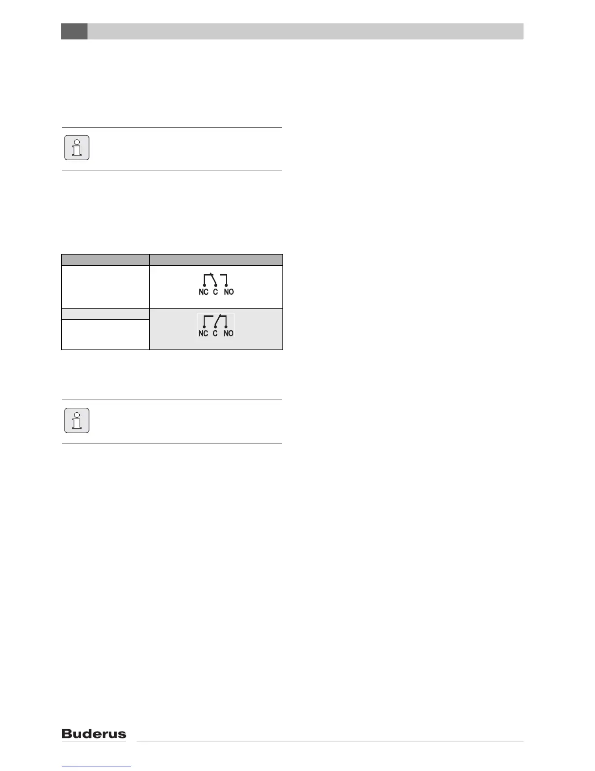
Situation Operating status contact
Current on, no fault
Current on, fault
No current
Tab. 8 Operating status contact
The remote fault indication is enabled when
the power supply to the MCM10 module is
interrupted (master) (function check).

 Loading...


