3
Installation
MCM10
11
B Hook in the MCM10 module at the top attachment
screw and secure with the two lower screws.
B With the use of stiff or flexible ducts:
– Remove all plastic grommets from the slits on the
lower side of the MCM10;
– push the duct connection to the intended place;
– break out the required number of cable entries by
knocking cautiously with a screwdriver handle;
– mount the duct according to the manufacturer's
instructions.
Note: When using ducts, no plastic grommets are
required.
3.2 Making the electrical connections
B Observe electrical code for the connection and use at
least cable AWG14 for the main power cord.
B Always route cables through the preassembled
grommets and apply the strain relief supplied to protect
the system against the ingress of dripping water.
B Wiring preferably with single core cable. When using
multi-strand (flexible) cables, fit them with wire ferrules.
B Cables can be pulled off the contact strip for their
connection to the screw terminals. The connectors are
color-coded and keyed to prevent mismatch of cable
terminals.
3.2.1 Connection of the low voltage part with
BUS connections
The minimum permissible cable cross-section of the 2-
wire BUS connection arises from the cable length:
B Route all low-voltage cables separately from cables
carrying 120V to avoid inductive interference (minimum
separation 4 inches)(100 mm).
B In case of inductive external influences, use shielded
cables.
This way, the cables are screened against external
influences (e.g. high-voltage cables, contact wires,
transformer stations, radio and TV devices, amateur
radio stations, microwave devices, etc.).
B When sensor leads are extended, apply the following
lead cross-sections:
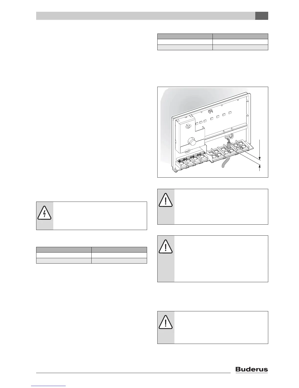
B To safeguard the splash-proof rating (IP):
Route cables so that the cable sheath protrudes at
least 0.8" (20 mm) into the cable grommet (Æ Fig. 9)
or the duct connection box.
Fig. 9 Splash-proof
3.2.2 120 V AC connection
B Only use electric cable of similar quality.
B Never connect additional controllers that regulate other
system components to outputs C (pump) and D (fault
signal).
CAUTION: Malfunction!
B Always wire in accordance with the wiring
diagram (Æ Fig. 12, page 19).
B Never connect one BUS to another.
Cable length Min. cross-section
< 325 ft (100 m) AWG 20
325 - 650 ft (100 - 200 m) AWG 18
Tab. 6 Minimum permissible cross-section of the
2-wire BUS connections
Cable length Min. cross-section
< 65 ft (20 m) AWG 20
65 - 100 ft (20 - 30 m) AWG 18
Tab. 7 Sensor lead extension
CAUTION: Risk of pole reversal.
Malfunction through interchanged
connection on the 0 - 10 V interface.
B Ensure connection to the correct poles
(9 = negative, 10 = positive).
CAUTION: The MCM10 module input is not
fuse-protected.
Overloading the outputs can damage the
MCM10 modules.
B Protect the MCM10 module power supply
(master) with a fuse with maximum rating
10 Amp.
CAUTION: Output C (pump) of the MCM10
module has a maximum load capacity of
250 W.
B Connect pumps drawing more current via
relays.
6 720 617 648 - 04.1O
≥1" (25 mm)

 Loading...


