5
Operating and fault indications
MCM10
14
5 Operating and fault indications
Operating state and faults can be indicated in four
different ways:
• via the heating appliance displays;
• via the remote fault indication;
• via the LEDs on the MCM10 module;
• via the display of the RC35 system controller.
5.1 Operating and fault indications via
the heating appliance displays
The operating and fault indications for each heating
appliance can be checked via the heating appliance
displays. For further details about the operating and fault
indications, see the heating appliance documentation.
5.2 Fault message via the remote fault
indication
For example, a fault indicator can be connected to the
zero volt fault contact (Æ paragrahp 3.2.3, page 12). The
state of the remote fault indication is also shown via an
LED on the MCM10 (Æ Tab. 9, page 14).
5.3 Operating and fault indications via
LED
Generally, three different states in the overall system can
be identified:
• Configuration (during start-up and after a reset);
• standard operation;
• fault.
Depending on the state of the overall system, the LEDs on
the MCM10 module (Æ Fig. 10, page 14) provide
indications about the operating and fault state of
individual components, and thereby enable specific
troubleshooting (Æ Tab. 9, page 14).
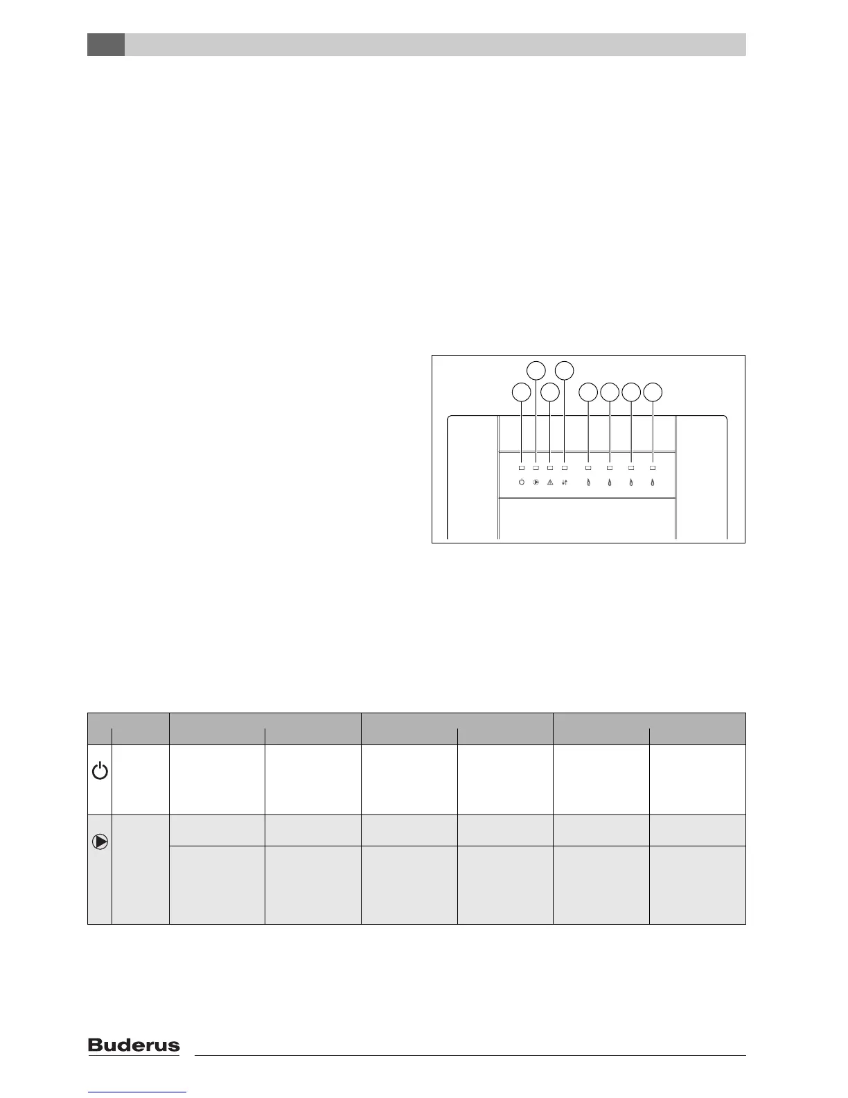
Fig. 10 Operating and fault indications via LED
1 Line voltage (green)
2 Heating pump (secondary zone) (green)
3 Switching contact for remote fault indication 120 VAC
(red)
4 Communication between MCM10s (green)
5 Heating appliance 1 (green)
6 Heating appliance 2 (green)
7 Heating appliance 3 (green)
8 Heating appliance 4 (green)
7 746 800 090-10.1O
1
2
3
4
5 6 7 8
LED OFF ON Flashing
No. Function Diagnosis Remedy Diagnosis Remedy Diagnosis Remedy
1 Line volt-
age
Fault: No line volt-
age.
Check power sup-
ply.
Replace MCM10
module.
Operation: Stan-
dard operation.
–
2 Heating
pump
Operation: Pump
OFF
Operation: Pump
ON.
–
Fault: Pump will not
start although the
LED is ON, as the
fuse for pump out-
put has blown.
Replace fuse
(Æ paragrahp 5.5,
page 17).
Tab. 9 Operating and fault indications on the MCM10 module

 Loading...


