2
Details about the MCM10 module
MCM10
8
System version 1: Modulating weather-
compensated heating controller (RC35)
An advantage of this system is the ability of the modules
to communicate, enabling all heating zones to be
controlled (function module WM10 or MM10) with the
MCM10 module via a common BUS, parallel to terminal J
on the MCM10 module (Æ Fig. 12, page 19). This
ensures matching generated heat amount to the actual
heat demand of all heating zones in the system. With this
version, the heating system achieves optimum comfort
with maximum energy savings.
System version 2: Modulating weather-
compensated heating controller (AM10)
The supply target temperature of the AM10 module
depends on the outdoor temperature. In contrast to
system version 1, it is not possible to use the WM10 and
MM10 modules.
System version 3: Modulating 0 - 10 V controller,
regulated acc. to output
In conjunction with a building management system with
0 - 10 V interface, the total output of the cascade can be
selected as control variable. Setting is achieved via a
jumper (Æ Fig. 3).
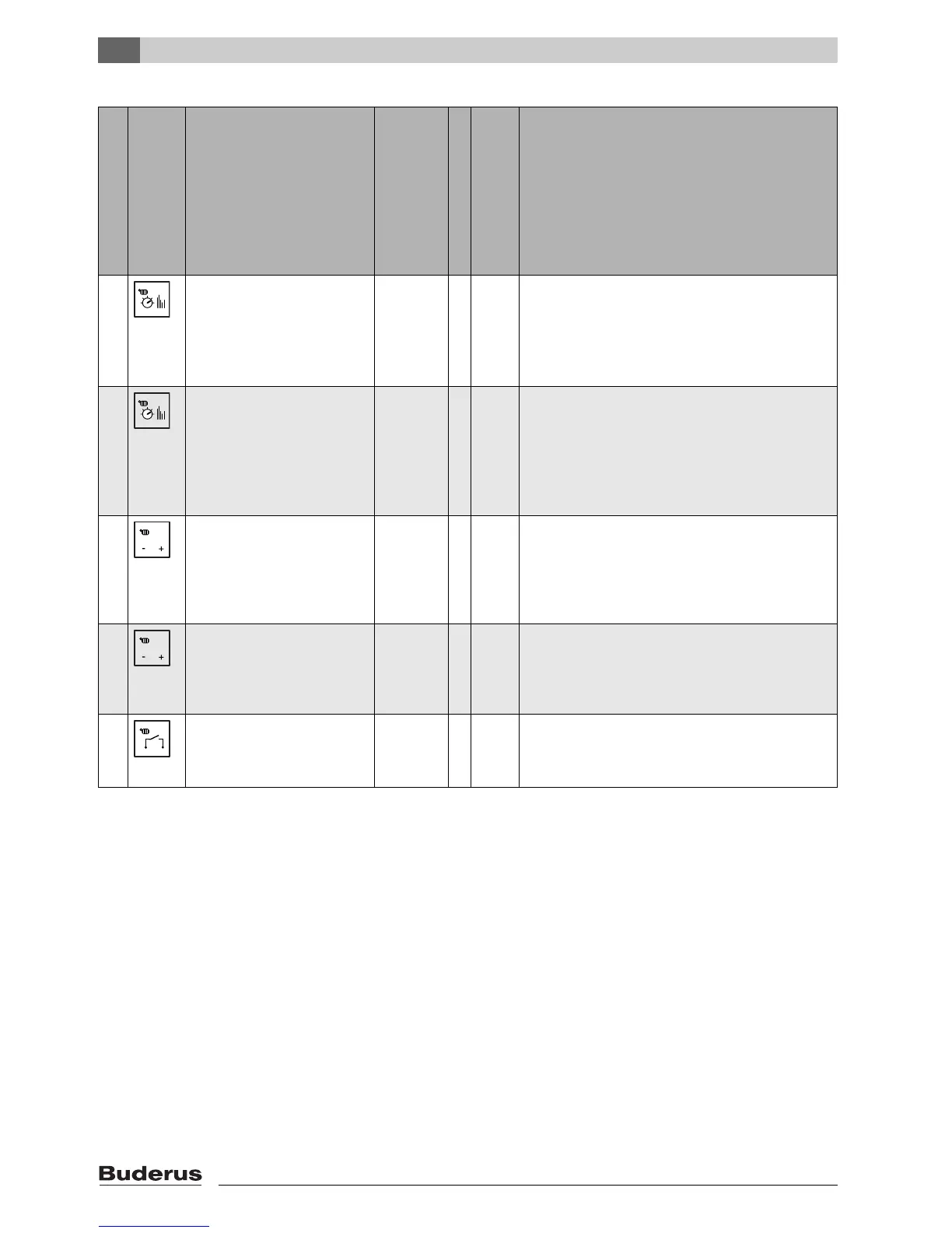
System version
Symbol forcontroller
connection
Heating controller to MCM10
master module
Type
Max. number MCM10
Max. number of heating
applianceswith BUS-enabled
Logamatic EMS
Required accessories with connection to MCM10
(Æ Fig. 12, page 19)
1 Modulating weather-compensated
controller 2-wire BUS control
RC35 4 16 • Outdoor temperature sensor.
• One WM10 module. The WM10 module is delivered with a
supply temperature sensor (see explanation on the following
page).
• Heating pump (secondary zone) is connected to the WM10
module.
2 Modulating weather-compensated
controller 2-wire BUS control
AM10
weather-
compen-
sated con-
troller
4 16 • Connect outdoor temperature sensor to AM10.
• Common supply temperature sensor on terminal E (only for
internal frost protection).
• Heating pump (secondary zone) (Æ Fig. 12, [19]) on termi-
nal C, only in case of one or several heating zones without
heating pump or in case of heating zones that do not com-
municate via BUS modules with the MCM10module.
3 Modulating
0 - 10 V controller,e.g. building man-
agement system;
control of the heat output
Any 4 16 • Common supply temperature sensor on terminal E (only for
internal frost protection).
• Heating pump (secondary zone) (Æ Fig. 12, [19]) on
terminal C, only with one or several heating zones without
heating pump or with heating zones that are not regulated
via the building management system.
4 Modulating
0 - 10 V controller, e.g. building man-
agement system;
supply temperature control
Any 4 16 • Common supply temperature sensor on terminal E
• Heating pump (secondary zone) (Æ Fig. 12, [19]) on
terminal C, only with one or several heating zones without
heating pump or with heating zones that are not regulated
via the building management system.
5 ON/OFF controller (zero volt) Any 4 16 • Common supply temperature sensor on terminal E (only for
internal frost protection).
• Heating pump (secondary zone) (Æ Fig. 12, [19]) on
terminal C.
Tab. 5 System versions overview
0 ... 10V
0 ... 10V

 Loading...


