5
Installation
S 32/5 – 6 720 804 007 (2014/10)10
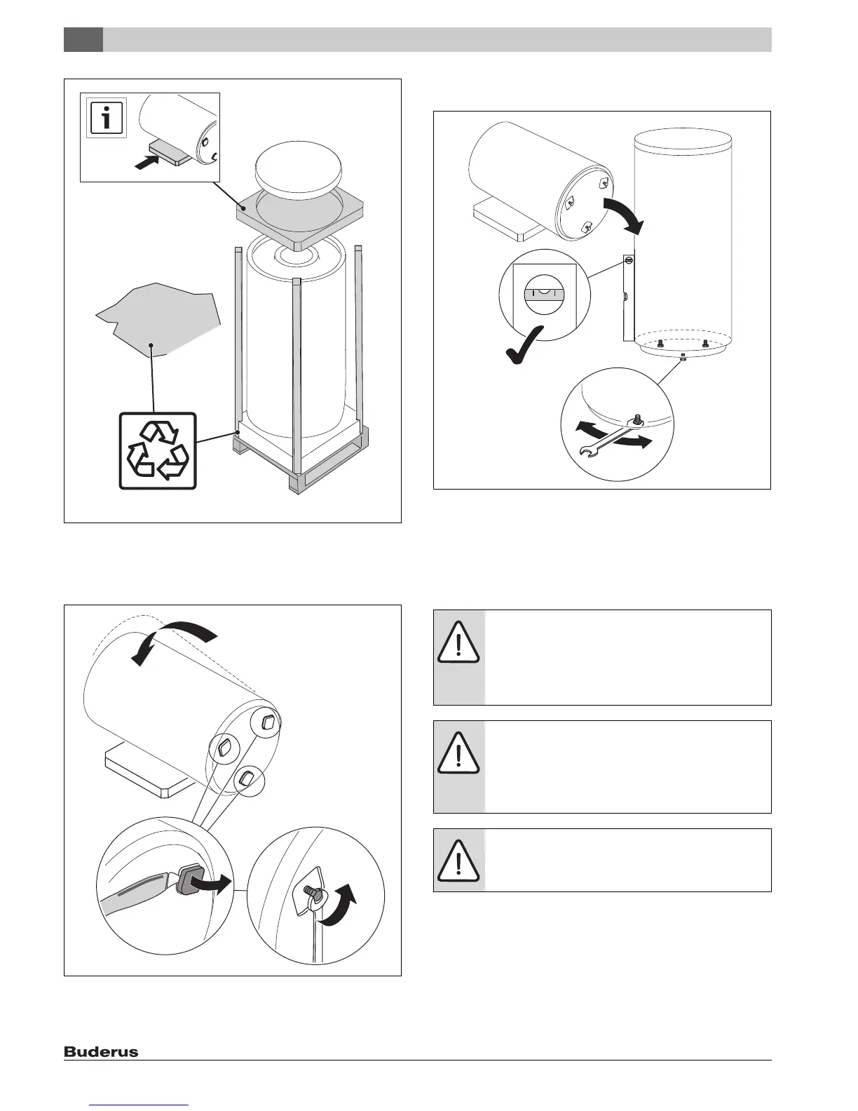
Fig. 6 Unpacking the tank
▶ Carefully lay the tank on the foam pad ( Fig. 7, [1]).
▶ Cut out the projections in the foam bottom ( Fig. 7, [2]).
▶ Unscrew the adjustable feet [3].
Fig. 7 Lay down the DHW tank and expose the adjustable feet
▶ Position the tank on a level floor that has adequate load-bearing
capacity ( Fig. 8).
Fig. 8 Positioning the tank
▶ Adjust the adjustable feet so that the DHW tank is vertical ( Fig. 8).
▶ Remove the caps from the connections.
▶ Use Teflon tape or Teflon cord to seal the connections. Do not use
hemp to seal the connections.
5.2 Water connections
6 720 801 769-15.1ITL
1.
2.
3.
DANGER: Risk of injury from contaminated water!
Work carried out without due care for cleanliness
contaminates the drinking water.
▶ Install in accordance with national standards and
guidelines.
WARNING: Risk of fire from soldering and brazing!
▶ Take appropriate safety measures when soldering
and brazing as the thermal insulation is flammable.
For example, cover up the thermal insulation.
▶ Check tank jacket for damage after completing work.
NOTICE: Risk of corrosion from damage to the enamel
coating!
▶ Tighten connections to the tank only "hand-tight".
6 720 801 769-13.1ITL

 Loading...