6
INSTALLATION INSTRUCTIONS
READ CAREFULLY BEFORE ASSEMBLY AND OPERATION OF YOUR SINGLE SIDEBURNER
Your single side burner comes to you fully assembled. We strongly recommend professional installation and hookup of
the single side burner. These instructions will provide you with the measurements necessary for you or your builder to
construct a masonry structure to house your outdoor single side burner.
NOTE TO INSTALLER: Leave these instructions with the consumer for future reference. The single side burner must
be installed in accordance with all local building codes. Adapter from 1/2” NPT to BSP 21 mm & regulator are available
from Bull dealers and distributors.
SPECIFICATIONS FOR SINGLE SIDEBURNER STRUCTURE
1. Your choice of masonry can be used for cabinet construction for the single side burner; however it must be non-
combustible material. Keep in mind when choosing a location for your single side burner that it should NOT be located
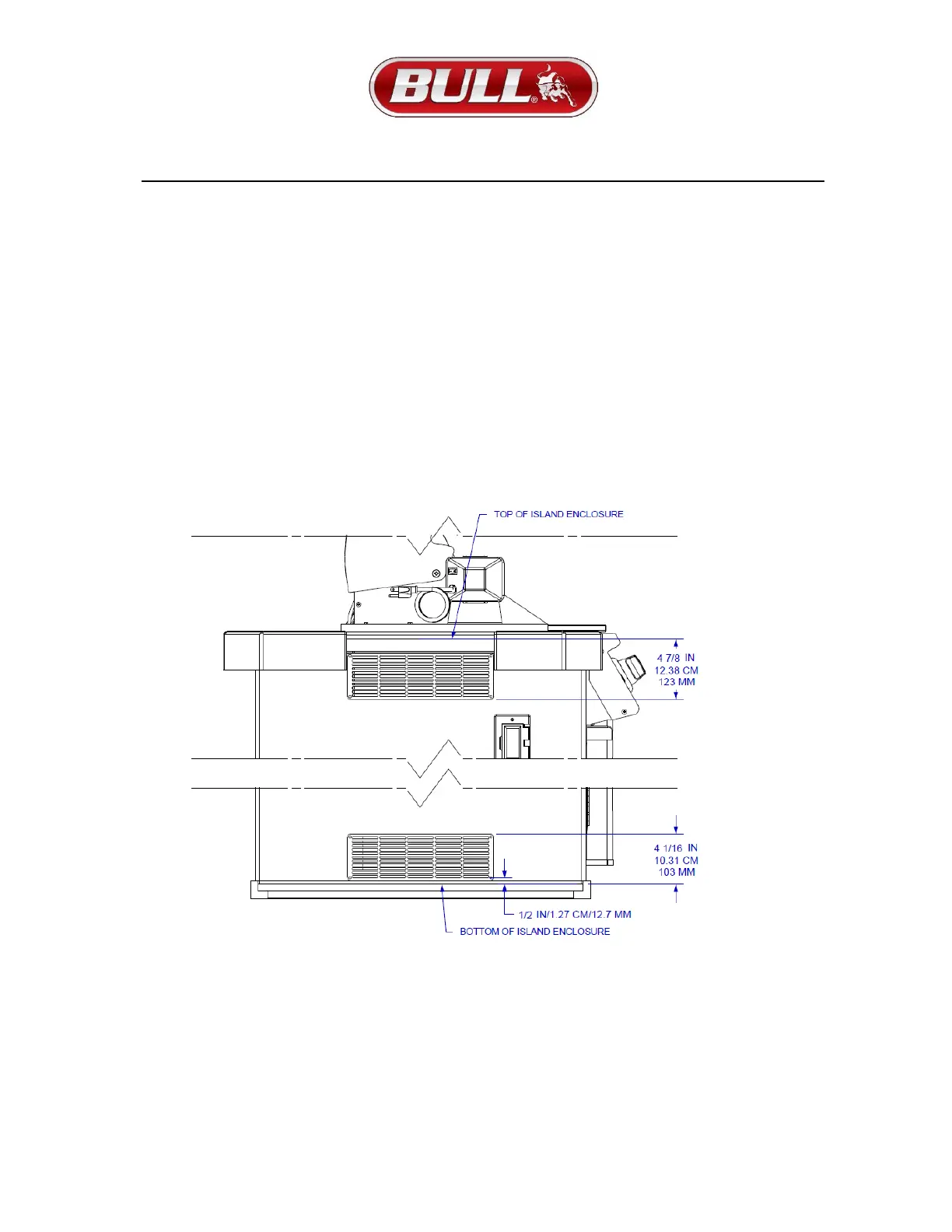
under any overhead combustible construction. Upper and lower level vents must be provided for combustion air on both
sides of built-in cabinet. Vents on single side burner insert must remain unobstructed to allow for combustion air and
ventilation. Upper vents must be located within 5 inches/12.7 cm/127 mm from the top of the island enclosure to the
bottom of the vent. Lower vents must be located within 1 inch/2.54 cm/25.4 mm from the bottom of the island enclosure
to the bottom of the first vent openings and no more than 5 inches/12.7 cm/127 mm from the bottom of the island
enclosure to the top of the vent. If not using Bull vents, the vents you use must meet ANSI Standard codes. The upper
vents must have openings that have a total free area of not less than 1 sq in/6.45 sq cm/645 sq mm per lb./kg of stored
fuel capacity per vent and the lower vents must have openings that have a total free area of not less than 1/2 sq in/3.22
sq cm/322 sq mm per lb./kg of stored fuel capacity per vent. Both upper and lower vent openings must have minimum
dimensions so as to permit the entrance of a 1/8 in/.31 cm/3.17 mm diameter rod.
2. The single side burner requires a wall opening of the following dimensions: See PAGES 7 & 8 for different models.
3. Place single side burner assembly into wall opening as shown in illustration on pages 7 & 8. The single side burner rests on
the front, back and
side edges of the insert.
4. For propane gas LP TANK STORAGE AREA MUST BE ISOLATED FROM SINGLE SIDE BURNER AND VENTED.
5. Do not use any combustible materials for this construction. Minimum horizontal clearance to adjacent combustible
surface from side and back of the single side burner must be 21 inches/54 cm/533 mm. A 6 inch/15 cm/152 mm
clearance is required behind the
side burner to allow for ventilation purposes.


 To Next Page