7
INSTALLATION INSTRUCTIONS (CONT.)
CONNECTING TO GAS SOURCE
Refer to the following instructions and illustrations for typical gas supply connections.
We strongly suggest professional installation and hook-up of the Gas BBQ.
IMPORTANT: Before connecting grill to gas source, make sure BBQ Grill control knobs are in “OFF” position.
Be sure to follow instructions for connecting an appliance to a fixed fuel piping system specifying the use of a
rigid pipe, semi-rigid tubing, and/or a connector that complies with the Standard for Connectors for Outdoor Gas
Appliances and Manufactured Homes, ANSI Z21.75 For post-mounted outdoor cooking gas appliances, in-
ground metallic posts shall be protected against corrosion as warranted by soil conditions. A suitable coating of
corrosion protection will retard the effects of corrosion and help your Bull purchase last longer.
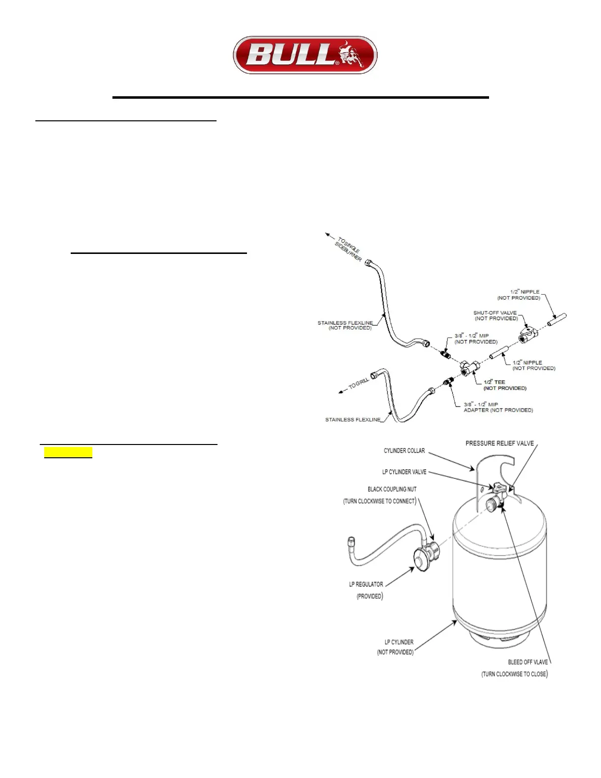
NATURAL GAS CONNECTIONS
IMPORTANT: Bull Outdoor Products does not
recommend the use of any quick connect fittings or
lines to the unit. Use of these types of fittings or
lines could cause low gas flow and greatly reduce
the performance of the unit.
1) Do not use Teflon ® tape or pipe sealant on any flare ends
because you will not obtain a leak-free seal.
2) Remove plastic cap from regulator installed on grill.
3) Attach stainless steel flex line 3/8” flare-female end to the regulator.
4) Attach the other end of flex line to shut-off valve through a nipple.
5) Attach a shut-off valve to gas supply pipe.
PERFORM GAS LEAK CHECK – REFER TO PAGE 3
PROPANE GAS CONNECTIONS
CAUTION: Changing the gas tanks must be done away
from any source of ignition.
1) LP Gas Tank must be marked in accordance with the
Specifications for LP Gas Cylinders, Spheres and Tubes for
Transportation of Dangerous Goods and Commission LP Gas
Tank connection device is compatible with outdoor cooking
appliances.
2) LP Gas Tank has appropriate vapor withdrawal.
3) LP Gas Tank must include a collar to protect the cylinder valve.
4) LP Gas Tank uses a type 1 tank valve that is firmly secured in an
upright position.
5) LP Gas pressure regulator and hose assembly supplied
with this unit must be used without alteration and must be
less than 59 inches in length.
6) If the hose assembly needs to be replaced, use only the type 1
specified in the parts list supplied with this unit.
7) To connect, turn the black coupling nut of the hose and regulator
assembly in a clockwise direction (see illustration below) until it
is completely threaded onto the cylinder valve before turning
gas supply on.
8) LP Gas Tank must have a listed overfilling prevention device.
PERFORM GAS LEAK CHECK – REFER TO PAGE 3