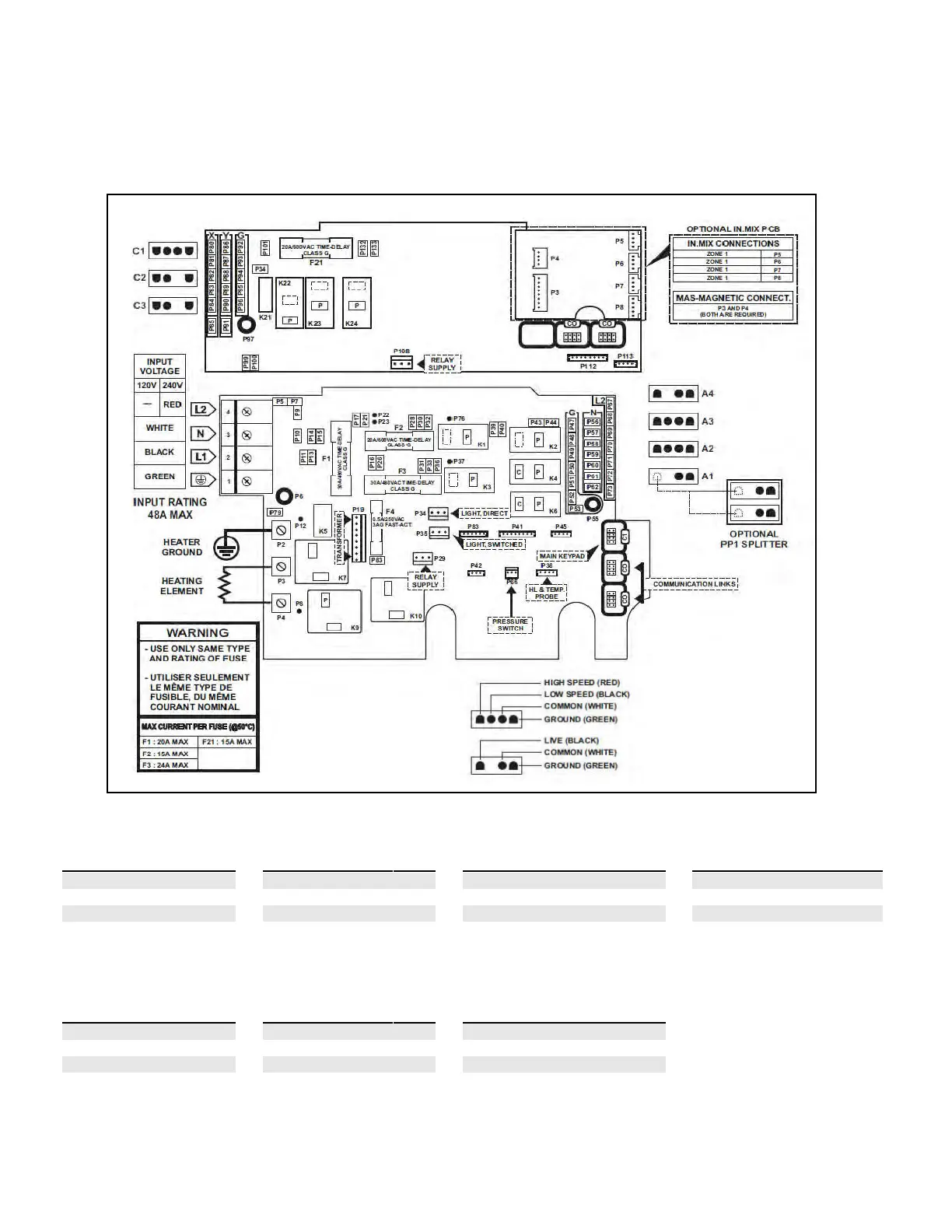
EasyManua.ls Logo

BullFrog A7 - Hardware Setup and Wiring; M Series Hardware Setup;Wiring

Default Icon
72 pages
Print Icon
To Next Page IconTo Next Page
To Previous Page IconTo Previous Page
Loading...
53
(yt9)
YT-9ULWiringDiagram
Pump1(A2)
Pump2(A3)
Pump3(C1)
Circulationpump/O3(A1)

Voltage
240V

Voltage
240V

Voltage
240V

Voltage
240V

Green/ground
G

Green/ground
G

Green/ground
G

Green/ground
G
Black/lowspeed
K6
Black/lowspeed
K2
Black/lowspeed
K22
Black/lowspeed
K1

Red/highspeed
K3

Red/highspeed
K4

Red/highspeed
K23

White/common
L2
White/common
L2
White/common
L2
White/common
L2
WaterfallPump(C2)
Externallight(C3)
Directoutput(A4)

Voltage
240V

Voltage
240V

Voltage
240V

Green/ground
G

Green/ground
G

Green/ground
G
Black/lowspeed
P34
Black/lowspeed
K24
Black/lowspeed
P28,P30,P32

White/common
L2

White/common
L2

White/common
L2
(North America 60 Hz)
NOTE: Spa models with 3 jet pumps (M9, M8, A9L) require a 60A service for full functionality. ese models may
alternatively be operated with various electrical congurations, however, certain set ups may result in operation limitations.
Setups that use three 16A circuits or two 20A circuit are preferred. Alternatively a setup using two 16A circuits can be used,
however some minor performance dierences will occur, contact your dealer for details.

Other manuals for BullFrog A7

Related product manuals