60
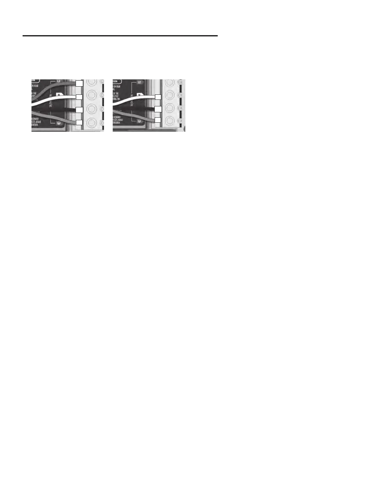
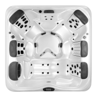
GFCI WIRING DIAGRAMS
240 V (4 wires)
120 V (*3 wires)
* If connected to a 3 wires
system, the heat.wave and
accessories will not operate
at 240 V.
Refer to the section
« Connections for 120 V
heaters ».
Note: To convert model to a 120 V system, the white (common)
accessory wire must be moved. See wiring diagram for details.
Electrical wiring: North Amercian model in.ye and in.yt
Refer to wiring diagram in the enclosure box lid for more information.
Insert each wire into the appropriate socket of the main entry terminal block according to the color code indicated on the
sticker. Use a flat-head screwdriver to tighten the screws on the terminal.
After making sure wires are securley connected, push them back into the box and replace the cover. Do not over tighten
cover screws (torque to 8 in. lb max {0.9 N.m}).
Connect the bonding conductor to the bonding lug on the front of the spa pack (a grounded electrode conductor should
be used to connect the equipment grounding conductors).
N N
L1
L1
L2
G
G
NOTE: On initial connection the installer is prompted for electrical congurations. e Low-Level setting is selected by the
installer. e Phase and Amperage is set automatically. Default settings should be conrmed by the installer to match the actual
phase and amperage at the spa’s installation location. In rare occasions it may be necessary to adjust the Phase and Amperage
setting to match the actual service available at the installation location using the Electrical Conguration instructions for your
spa’s specic control system. e "Input Amperage" for a 60A service is 48. e "Input Amperage" for a 50A service is 40.