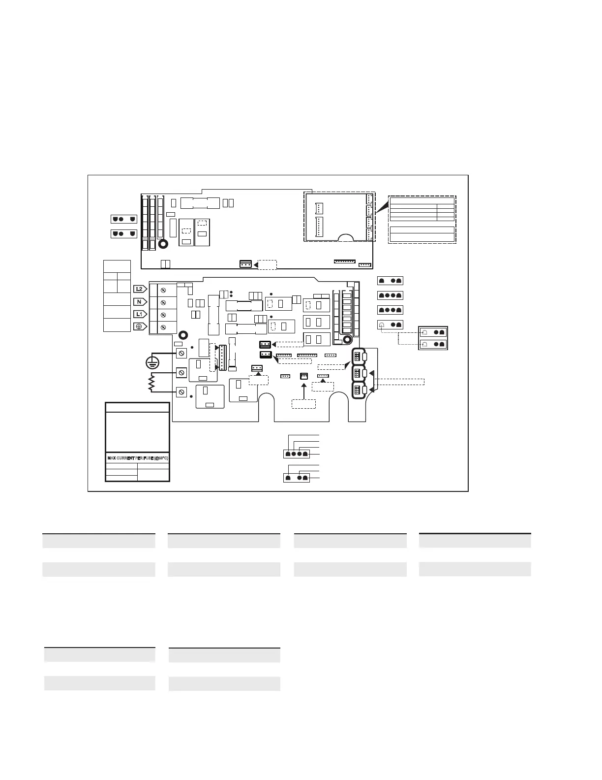
Connecting high voltage accessories: North American model in.yt
For the connection to the 0.250 inch terminals, the high voltage accessories must be provided with female quick
connect terminals, straight and non-insulated for all types of connections, including the ground. Accessories of 120 V or
240 V may be connected to the corresponding terminals of the printed circuit of the in.yt. Refer to the following tables
for correct connections. Note that all female terminals must be correctly and completely seated on the printed circuit
terminals for proper current ratings.
C3
A3
A4
A1
A2
C2
- USE ONLY SAME TYPE
AND RATING OF FUSE
- UTILISER SEULEMENT
LE MÊME TYPE DE
FUSIBLE, DU MÊME
COURANT NOMINAL
WARNING
MAX CURRENT PER FUSE (@50°C)
F2 : 15A MAX
F3 : 24A MAX
F1 : 20A MAX
F21 : 15A MAX
HIGH SPEED (RED)
LOW SPEED (BLACK)
COMMON (WHITE)
GROUND (GREEN)
LIVE (BLACK)
COMMON (WHITE)
GROUND (GREEN)
120V 240V
---
RED
WHITE
BLACK
GREEN
INPUT
VOLTAGE
INPUT RATING
48A MAX
P113
P112
P108
F21
20A/600VAC TIME-DELAY
CLASS G
K22
P
P80P81P82P83P84
P92P93P94P95P96
P87P88P89P90
P85
P91 P86
X Y G
P97
P99
P100
K23
P
P101
P34
P133
P132
K21
RELAY
SUPPLY
LED OUTPUT
OPTIONAL IN.MIX PCB
P4
P3
P5
P6
P7
P8
OPTIONAL
PP1 SPLITTER
K3
K4
K6
K7
K9
K10
P5
P17
P7
P22
P23
P28
P30
P33
P36
P37
P34
P6
P2
P3
P4
P8
P29
P41
P42
P45
P35
30A/480VAC TIME-DELAY
CLASS G
F2
20A/600VAC TIME-DELAY
CLASS G
30A/480VAC TIME-DELAY
CLASS G
F3
F1
F4
1
2
3
4
0.5A/250VAC
3AG FAST-ACT.
P
K1
K2
P39
P40
P43 P44
P
P
P
P
CO C1CO
P9
P10
P11
P13
P14
P15
P21
P32
P31
C
C
P12
P66
P47
G N
L2
P48P49P50P51P52
P53
P56
P57
P58
P59
P60
P61
P62
P67P68P69P70P71P72
P73
P55
P
P76
P26
P16
P79
P83
TRANSFORMER
LIGHT, SWITCHED
PRESSURE
SWITCH
MAIN KEYPAD
LIGHT, DIRECT
P83
RELAY
SUPPLY
P38
HL & TEMP.
PROBE
P19
K5
COMMUNICATION LINKS
HEATING
ELEMENT
HEATER
GROUND
L1
N
L2
Pump 2 (A3)
Voltage 240 V
Green / ground G
Black / low speed K2
Red / high speed K4
White / common L2
Pump 3 L120 (C3)
Voltage 240 V
Green / ground G
Black / low speed K23
White / common L2
Pump 1 (A2)
Voltage 240 V
Green / ground G
Black / low speed K6
Red / high speed K3
White / common L2
Circulation pump (A1)
Voltage 240 V
Green / ground G
Black / line K1
White / common L2
Ozonator (C2)
Voltage 240 V
Green / ground G
Black / line K22
White / common L2
Direct output 1 (A4)
Voltage 240 V
Green / ground G
Black / line P32
White / common L2