16
Installation
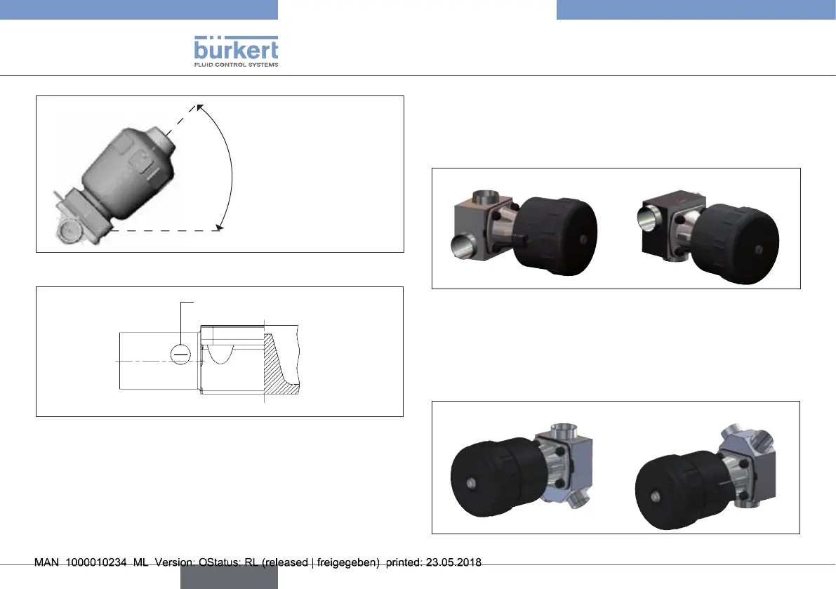
Angle α: 10° to 40°
Inclination to the
line axis 1° ... 5°
Fig. 12: Installation position for self-drainage of the body
Mark for self-drainage
angle
Fig. 13: Mark for the correct installation position
8.2.3 Installation position of T-valve
Type 2032
For the installation of the T-valves into circular pipelines, we rec-
ommend the following installation positions:
When media is supplied: When media is removed:
Fig. 14: Installation position of type 2032
8.2.4 Installation position of Y-valve
Type 2037
For the installation of the Y-valves into systems, we recommend the
following installation positions:
When media is supplied: When media is removed:
Fig. 15: Installation position of type 2037
english
Type 2030, 2031, 2031 K, 2032,
2033, 2037